ASME B16.5, ASME B16.47 Series A and Series B RTJ Flange Supplier
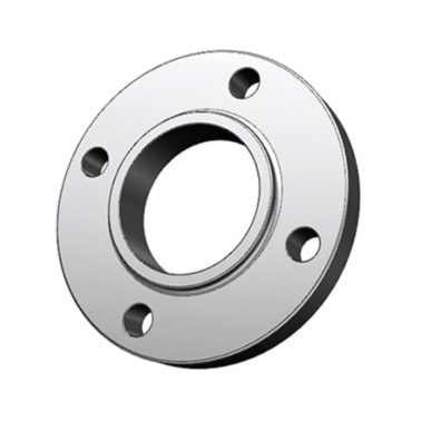
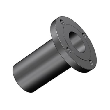
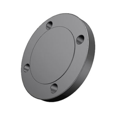
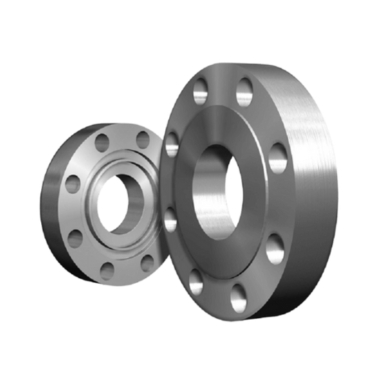
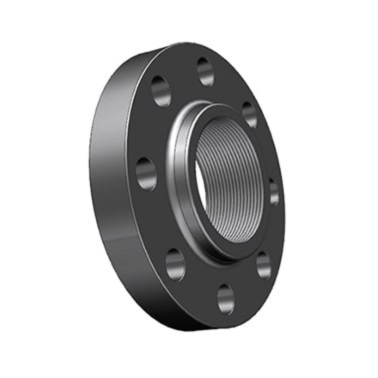
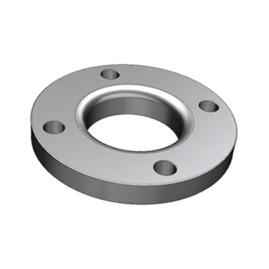
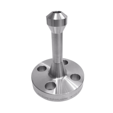
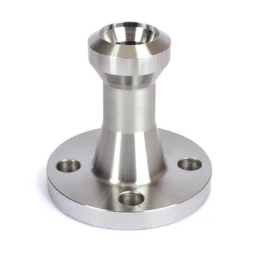
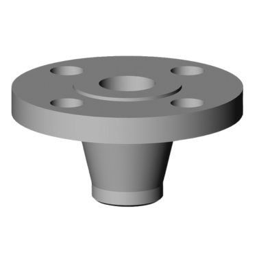
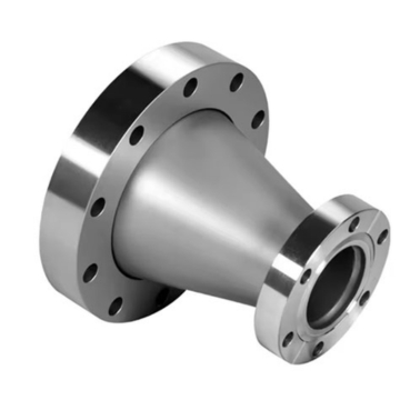
A Ring Type Joint Flange is a specialized flange designed for high-pressure, high-temperature applications where a strong, reliable seal is crucial. These flanges feature a groove in the face that accommodates a ring-shaped gasket, typically made from metal, which forms a tight seal when the flanges are bolted together. RTJ flanges are commonly used in industries such as oil and gas, petrochemical, and chemical processing, where they provide leak-proof connections in demanding environments. They are available in various sizes and materials, including carbon steel, stainless steel, and alloy steels, to suit specific system requirements. RTJ flanges are designed to meet rigorous international standards like ASME B16.5, ensuring their durability and performance under extreme conditions.
Ample Alloys is a leading Manufacturer, supplier of high-quality RTJ Flanges, offering reliable and durable solutions for industries that require secure, high-pressure connections. With years of expertise in the manufacturing and distribution of flanges, We ensures that all RTJ flanges are made with precision and meet international standards, including ASME B16.5. We are known for commitment to quality control, timely delivery, and customization options, making a trusted choice for customers looking for dependable RTJ flanges for applications. With an emphasis on customer satisfaction and technical expertise, Ample Alloys is the go-to supplier for premium RTJ flanges tailored to meet the toughest operational demands.
API Ring Type Joint Flange, RTJ Flange for high pressure, Forged Ring Type Joint Flange, Stainless Steel Ring Type Joint Flange, RTJ Flange welding, RTJ Flange API 6A, RTJ Flange with groove, Flange RTJ sealing surface finish
ASME/ANSI B16.5 RTJ Flange
Size Range
15mm ( 1/2" NPS ) up to 600mm ( 24" NPS ), For 2500# in sizes from NPS 1/2 to NPS 12
Flange Face Type
FF—Flat Face, RF—Raised Face, FM—Female Face, M—Male Face, T—Tongue Face, G—Groove Face, RJ—Ring Joint.
Stainless Steel
ASTM A182 F 304, 304L, 304H, 316, 316L, 316H, 317, 317L, 321, 321H, 310, 310S, 347, 904L, etc.
Standards / Dimension
ANSI/ASME B16.5, B 16.47 Series A & B, B16.48, BS4504, BS 10, EN-1092, DIN
Carbon Steel
ASTM A105/A105N (SA105N), LTCS A350 LF2, A694
Alloy Steel
ASTM A182 / SA182 - F1 / F5 / F9 / F11 / F12 / F22 / F91
Pressure Class
150#, 300#, 600#, 900#, 1500#, 2500#, PN6, PN10, PN16, PN25, PN40, PN64.
Duplex & Super Duplex
ASTM A182 / ASME SA182 - S31803, S32205, 2205, S32750, S32760, S32950, 2507.
MTC
EN 10204 3.2 and EN 10204 3.1, Test Certificates certifying NACE MR0175, NACE MR0103
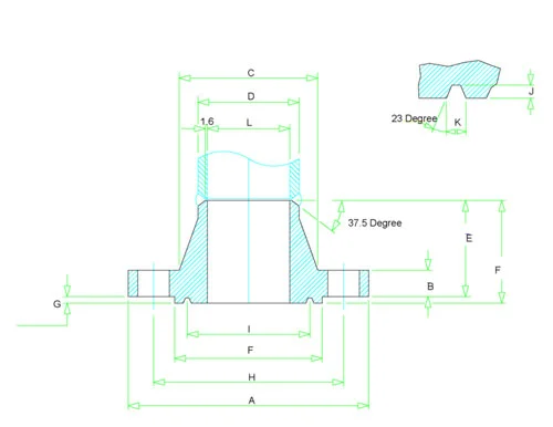
| Size in Inch | Size in mm | Outer Dia. | Flange Thickness | Hub OD | Weld Neck OD | Welding Neck Length | RTJ RF Dia | RTJ RF Height | PCD | RTJ Pitch dia | RTJ Depth | RTJ Width | Bore |
|---|---|---|---|---|---|---|---|---|---|---|---|---|---|
| A | B | C | D | E | F | G | H | I | J | K | L | ||
| 1/2 | 15 | 90 | 9.6 | 30 | 21.3 | 46 | N/A | N/A | 60.3 | N/A | N/A | N/A | Welding Neck bore is derived from the pipe schedule |
| 3/4 | 20 | 100 | 11.2 | 38 | 26.7 | 51 | N/A | N/A | 69.9 | N/A | N/A | N/A | |
| 1 | 25 | 110 | 12.7 | 49 | 33.4 | 54 | 63.5 | 6.35 | 79.4 | 47.63 | 6.35 | 8.74 | |
| 1 1/4 | 32 | 115 | 14.3 | 59 | 42.2 | 56 | 73 | 6.35 | 88.9 | 57.15 | 6.35 | 8.74 | |
| 1 1/2 | 40 | 125 | 15.9 | 65 | 48.3 | 60 | 82.5 | 6.35 | 98.4 | 65.07 | 6.35 | 8.74 | |
| 2 | 50 | 150 | 17.5 | 78 | 60.3 | 62 | 102 | 6.35 | 120.7 | 82.55 | 6.35 | 8.74 | |
| 2 1/2 | 65 | 180 | 20.7 | 90 | 73 | 68 | 121 | 6.35 | 139.7 | 101.6 | 6.35 | 8.74 | |
| 3 | 80 | 190 | 22.3 | 108 | 88.9 | 68 | 133 | 6.35 | 152.4 | 114.3 | 6.35 | 8.74 | |
| 3 1/2 | 90 | 215 | 22.3 | 122 | 101.6 | 70 | 154 | 6.35 | 177.8 | 131.78 | 6.35 | 8.74 | |
| 4 | 100 | 230 | 22.3 | 135 | 114.3 | 75 | 171 | 6.35 | 190.5 | 149.23 | 6.35 | 8.74 | |
| 5 | 125 | 255 | 22.3 | 164 | 141.3 | 87 | 194 | 6.35 | 215.9 | 171.45 | 6.35 | 8.74 | |
| 6 | 150 | 280 | 23.9 | 192 | 168.3 | 87 | 219 | 6.35 | 241.3 | 193.68 | 6.35 | 8.74 | |
| 8 | 200 | 345 | 27 | 246 | 219.1 | 100 | 273 | 6.35 | 298.5 | 247.65 | 6.35 | 8.74 | |
| 10 | 250 | 405 | 28.6 | 305 | 273 | 100 | 330 | 6.35 | 362 | 304.8 | 6.35 | 8.74 | |
| 12 | 300 | 485 | 30.2 | 365 | 323.8 | 113 | 406 | 6.35 | 431.8 | 381 | 6.35 | 8.74 | |
| 14 | 350 | 535 | 33.4 | 400 | 355.6 | 125 | 425 | 6.35 | 476.3 | 396.88 | 6.35 | 8.74 | |
| 16 | 400 | 595 | 35 | 457 | 406.4 | 125 | 483 | 6.35 | 539.8 | 454.03 | 6.35 | 8.74 | |
| 18 | 450 | 635 | 38.1 | 505 | 457.2 | 138 | 546 | 6.35 | 577.9 | 517.53 | 6.35 | 8.74 | |
| 20 | 500 | 700 | 41.3 | 559 | 508 | 143 | 597 | 6.35 | 635 | 558.8 | 6.35 | 8.74 | |
| 24 | 600 | 815 | 46.1 | 663 | 610 | 151 | 711 | 6.35 | 749.3 | 673.1 | 6.35 | 8.74 |
| Size in Inch | Size in mm | Outer Dia. | Flange Thickness | Hub OD | Weld Neck OD | Welding Neck Length | RTJ RF Dia | RTJ RF Height | PCD | RTJ Pitch dia | RTJ Depth | RTJ Width | Bore |
|---|---|---|---|---|---|---|---|---|---|---|---|---|---|
| A | B | C | D | E | F | G | H | I | J | K | L | ||
| 1/2 | 15 | 95 | 12.7 | 38 | 21.3 | 51 | 51 | 5.54 | 66.7 | 34.14 | 5.54 | 7.14 | Welding Neck bore is derived from the pipe schedule |
| 3/4 | 20 | 115 | 14.3 | 48 | 26.7 | 56 | 63.5 | 6.35 | 82.6 | 42.88 | 6.35 | 8.74 | |
| 1 | 25 | 125 | 15.9 | 54 | 33.4 | 60 | 70 | 6.35 | 88.9 | 50.8 | 6.35 | 8.74 | |
| 1 1/4 | 32 | 135 | 17.5 | 64 | 42.2 | 64 | 79.5 | 6.35 | 98.4 | 60.33 | 6.35 | 8.74 | |
| 1 1/2 | 40 | 155 | 19.1 | 70 | 48.3 | 67 | 90.5 | 6.35 | 114.3 | 68.27 | 6.35 | 8.74 | |
| 2 | 50 | 165 | 20.7 | 84 | 60.3 | 68 | 108 | 7.92 | 127 | 82.55 | 7.92 | 11.91 | |
| 2 1/2 | 65 | 190 | 23.9 | 100 | 73 | 75 | 127 | 7.92 | 149.2 | 101.6 | 7.92 | 11.91 | |
| 3 | 80 | 210 | 27 | 117 | 88.9 | 78 | 146 | 7.92 | 168.3 | 123.83 | 7.92 | 11.91 | |
| 3 1/2 | 90 | 230 | 28.6 | 133 | 101.6 | 79 | 159 | 7.92 | 184.2 | 131.78 | 7.92 | 11.91 | |
| 4 | 100 | 255 | 30.2 | 146 | 114.3 | 84 | 175 | 7.92 | 200 | 149.23 | 7.92 | 11.91 | |
| 5 | 125 | 280 | 33.4 | 178 | 141.3 | 97 | 210 | 7.92 | 235 | 180.98 | 7.92 | 11.91 | |
| 6 | 150 | 320 | 35 | 206 | 168.3 | 97 | 241 | 7.92 | 269.9 | 211.12 | 7.92 | 11.91 | |
| 8 | 200 | 380 | 39.7 | 260 | 219.1 | 110 | 302 | 7.92 | 330.2 | 269.88 | 7.92 | 11.91 | |
| 10 | 250 | 445 | 46.1 | 321 | 273 | 116 | 356 | 7.92 | 387.4 | 323.85 | 7.92 | 11.91 | |
| 12 | 300 | 520 | 49.3 | 375 | 323.8 | 129 | 413 | 7.92 | 450.8 | 381 | 7.92 | 11.91 | |
| 14 | 350 | 585 | 52.4 | 425 | 355.6 | 141 | 457 | 7.92 | 514.4 | 419.1 | 7.92 | 11.91 | |
| 16 | 400 | 650 | 55.6 | 483 | 406.4 | 144 | 508 | 7.92 | 571.5 | 469.9 | 7.92 | 11.91 | |
| 18 | 450 | 710 | 58.8 | 533 | 457 | 157 | 575 | 7.92 | 628.6 | 533.4 | 7.92 | 11.91 | |
| 20 | 500 | 775 | 62 | 587 | 508 | 160 | 635 | 9.53 | 685.8 | 584.2 | 9.53 | 13.49 | |
| 24 | 600 | 915 | 68.3 | 702 | 610 | 167 | 749 | 11.13 | 812.8 | 692.15 | 11.13 | 16.66 |
| Size in Inch | Size in mm | Outer Dia. | Flange Thickness | Hub OD | Weld Neck OD | Welding Neck Length | RTJ RF Dia | RTJ RF Height | PCD | RTJ Pitch dia | RTJ Depth | RTJ Width | Bore |
|---|---|---|---|---|---|---|---|---|---|---|---|---|---|
| A | B | C | D | E | F | G | H | I | J | K | L | ||
| 1/2 | 15 | 95 | 14.3 | 38 | 21.3 | 52 | 51 | 5.54 | 66.7 | 34.14 | 5.54 | 7.14 | Welding Neck bore is derived from the pipe schedule |
| 3/4 | 20 | 115 | 15.9 | 48 | 26.7 | 57 | 63.5 | 6.35 | 82.6 | 42.88 | 6.35 | 8.74 | |
| 1 | 25 | 125 | 17.5 | 54 | 33.4 | 62 | 70 | 6.35 | 88.9 | 50.8 | 6.35 | 8.74 | |
| 1 1/4 | 32 | 135 | 20.7 | 64 | 42.2 | 67 | 79.5 | 6.35 | 98.4 | 60.33 | 6.35 | 8.74 | |
| 1 1/2 | 40 | 155 | 22.3 | 70 | 48.3 | 70 | 90.5 | 6.35 | 114.3 | 68.27 | 6.35 | 8.74 | |
| 2 | 50 | 165 | 25.4 | 84 | 60.3 | 73 | 108 | 7.92 | 127 | 82.55 | 7.92 | 11.9 | |
| 2 1/2 | 65 | 190 | 28.6 | 100 | 73 | 79 | 127 | 7.92 | 149.2 | 101.6 | 7.92 | 11.9 | |
| 3 | 80 | 210 | 31.8 | 117 | 88.9 | 83 | 146 | 7.92 | 168.3 | 123.83 | 7.92 | 11.9 | |
| 3 1/2 | 90 | 230 | 35 | 133 | 101.6 | 86 | 159 | 7.92 | 184.2 | 131.78 | 7.92 | 11.9 | |
| 4 | 100 | 255 | 35 | 146 | 114.3 | 89 | 175 | 7.92 | 200 | 149.23 | 7.92 | 11.91 | |
| 5 | 125 | 280 | 38.1 | 178 | 141.3 | 102 | 210 | 7.92 | 235 | 180.98 | 7.92 | 11.91 | |
| 6 | 150 | 320 | 41.3 | 206 | 168.3 | 103 | 241 | 7.92 | 269.9 | 211.12 | 7.92 | 11.91 | |
| 8 | 200 | 380 | 47.7 | 260 | 219.1 | 117 | 302 | 7.92 | 330 | 269.88 | 7.92 | 11.91 | |
| 10 | 250 | 445 | 54 | 321 | 273 | 124 | 356 | 7.92 | 387.4 | 323.85 | 7.92 | 11.91 | |
| 12 | 300 | 520 | 57.2 | 375 | 323.8 | 137 | 413 | 7.92 | 450.8 | 381 | 7.92 | 11.91 | |
| 14 | 350 | 585 | 60.4 | 425 | 355.6 | 149 | 457 | 7.92 | 514.4 | 419.1 | 7.92 | 11.91 | |
| 16 | 400 | 650 | 63.5 | 483 | 406.4 | 152 | 508 | 7.92 | 571.5 | 469.9 | 7.92 | 11.91 | |
| 18 | 450 | 710 | 66.7 | 533 | 457 | 165 | 575 | 7.92 | 628.6 | 533.4 | 7.92 | 11.91 | |
| 20 | 500 | 775 | 69.9 | 587 | 508 | 168 | 635 | 9.53 | 685.8 | 584.2 | 9.53 | 13.49 | |
| 24 | 600 | 915 | 76.2 | 702 | 610 | 175 | 749 | 11.13 | 812.8 | 692.15 | 11.13 | 16.66 |
| Size in Inch | Size in mm | Outer Dia. | Flange Thickness | Hub OD | Weld Neck OD | Welding Neck Length | RTJ RF Dia | RTJ RF Height | PCD | RTJ Pitch dia | RTJ Depth | RTJ Width | Bore |
|---|---|---|---|---|---|---|---|---|---|---|---|---|---|
| A | B | C | D | E | F | G | H | I | J | K | L | ||
| 1/2 | 15 | 95 | 14.3 | 38 | 21.3 | 52 | 51 | 5.54 | 66.7 | 34.14 | 5.54 | 7.14 | Welding Neck bore is derived from the pipe schedule |
| 3/4 | 20 | 115 | 15.9 | 48 | 26.7 | 57 | 63.5 | 6.35 | 82.6 | 42.88 | 6.35 | 8.74 | |
| 1 | 25 | 125 | 17.5 | 54 | 33.4 | 62 | 70 | 6.35 | 88.9 | 50.8 | 6.35 | 8.74 | |
| 1 1/4 | 32 | 135 | 20.7 | 64 | 42.2 | 67 | 79.5 | 6.35 | 98.4 | 60.33 | 6.35 | 8.74 | |
| 1 1/2 | 40 | 155 | 22.3 | 70 | 48.3 | 70 | 90.5 | 6.35 | 114.3 | 68.27 | 6.35 | 8.74 | |
| 2 | 50 | 165 | 25.4 | 84 | 60.3 | 73 | 108 | 7.92 | 127 | 82.55 | 7.92 | 11.91 | |
| 2 1/2 | 65 | 190 | 28.6 | 100 | 73 | 79 | 127 | 7.92 | 149.2 | 101.6 | 7.92 | 11.91 | |
| 3 | 80 | 210 | 31.8 | 117 | 88.9 | 83 | 146 | 7.92 | 168.3 | 123.83 | 7.92 | 11.91 | |
| 3 1/2 | 90 | 230 | 35 | 133 | 101.6 | 86 | 159 | 7.92 | 184.2 | 131.78 | 7.92 | 11.91 | |
| 4 | 100 | 275 | 38.1 | 152 | 114.3 | 102 | 175 | 7.92 | 215.9 | 149.23 | 7.92 | 11.91 | |
| 5 | 125 | 330 | 44.5 | 189 | 141.3 | 114 | 210 | 7.92 | 266.7 | 180.98 | 7.92 | 11.91 | |
| 6 | 150 | 355 | 47.7 | 222 | 168.3 | 117 | 241 | 7.92 | 292.1 | 211.12 | 7.92 | 11.91 | |
| 8 | 200 | 420 | 55.6 | 273 | 219.1 | 133 | 302 | 7.92 | 349.2 | 269.88 | 7.92 | 11.91 | |
| 10 | 250 | 510 | 63.5 | 343 | 273 | 152 | 356 | 7.92 | 431.8 | 323.85 | 7.92 | 11.91 | |
| 12 | 300 | 560 | 66.7 | 400 | 323.8 | 156 | 413 | 7.92 | 489 | 381 | 7.92 | 11.91 | |
| 14 | 350 | 605 | 69.9 | 432 | 355.6 | 165 | 457 | 7.92 | 527 | 419.1 | 7.92 | 11.91 | |
| 16 | 400 | 685 | 76.2 | 495 | 406.4 | 178 | 508 | 7.92 | 603.2 | 469.9 | 7.92 | 11.91 | |
| 18 | 450 | 745 | 82.6 | 546 | 457 | 184 | 575 | 7.92 | 654 | 533.4 | 7.92 | 11.91 | |
| 20 | 500 | 815 | 88.9 | 610 | 508 | 190 | 635 | 9.53 | 723.9 | 584.2 | 9.53 | 13.49 | |
| 24 | 600 | 940 | 101.6 | 718 | 610 | 203 | 749 | 11.13 | 838.2 | 692.15 | 11.13 | 16.66 |
| Size in Inch | Size in mm | Outer Dia. | Flange Thickness | Hub OD | Weld Neck OD | Welding Neck Length | RTJ RF Dia | RTJ RF Height | PCD | RTJ Pitch dia | RTJ Depth | RTJ Width | Bore |
|---|---|---|---|---|---|---|---|---|---|---|---|---|---|
| A | B | C | D | E | F | G | H | I | J | K | L | ||
| 1/2 | 15 | 120 | 22.3 | 38 | 21.3 | 60 | 60.5 | 6.35 | 82.6 | 39.67 | 6.35 | 8.74 | Welding Neck bore is derived from the pipe schedule |
| 3/4 | 20 | 130 | 25.4 | 44 | 26.7 | 70 | 66.5 | 6.35 | 88.9 | 44.45 | 6.35 | 8.74 | |
| 1 | 25 | 150 | 28.6 | 52 | 33.4 | 73 | 71.5 | 6.35 | 101.6 | 50.8 | 6.35 | 8.74 | |
| 1 1/4 | 32 | 160 | 28.6 | 64 | 42.2 | 73 | 81 | 6.35 | 111.1 | 60.33 | 6.35 | 8.74 | |
| 1 1/2 | 40 | 180 | 31.8 | 70 | 48.3 | 83 | 92 | 6.35 | 123.8 | 68.27 | 6.35 | 8.74 | |
| 2 | 50 | 215 | 38.1 | 105 | 60.3 | 102 | 124 | 7.92 | 165.1 | 95.25 | 7.92 | 11.91 | |
| 2 1/2 | 65 | 245 | 41.3 | 124 | 73 | 105 | 137 | 7.92 | 190.5 | 107.95 | 7.92 | 11.91 | |
| 3 | 80 | 240 | 38.1 | 127 | 88.9 | 102 | 156 | 7.92 | 190.5 | 123.83 | 7.92 | 11.91 | |
| 4 | 100 | 290 | 44.5 | 159 | 114.3 | 114 | 181 | 7.92 | 235 | 149.23 | 7.92 | 11.91 | |
| 5 | 125 | 350 | 50.8 | 190 | 141.3 | 127 | 216 | 7.92 | 279.4 | 180.98 | 7.92 | 11.91 | |
| 6 | 150 | 380 | 55.6 | 235 | 168.3 | 140 | 241 | 7.92 | 317.5 | 211.12 | 7.92 | 11.91 | |
| 8 | 200 | 470 | 63.5 | 298 | 219.1 | 162 | 308 | 7.92 | 393.7 | 269.88 | 7.92 | 11.91 | |
| 10 | 250 | 545 | 69.9 | 368 | 273 | 184 | 362 | 7.92 | 469.9 | 323.85 | 7.92 | 11.91 | |
| 12 | 300 | 610 | 79.4 | 419 | 323.8 | 200 | 419 | 7.92 | 533.4 | 381 | 7.92 | 11.91 | |
| 14 | 350 | 640 | 85.8 | 451 | 355.6 | 213 | 467 | 11.13 | 558.8 | 419.1 | 11.13 | 16.66 | |
| 16 | 400 | 705 | 88.9 | 508 | 406.4 | 216 | 524 | 11.13 | 616 | 469.9 | 11.13 | 16.66 | |
| 18 | 450 | 785 | 101.6 | 565 | 457 | 229 | 594 | 12.7 | 685.8 | 533.4 | 12.7 | 19.84 | |
| 20 | 500 | 855 | 108 | 622 | 508 | 248 | 648 | 12.7 | 749.3 | 584.2 | 12.7 | 19.84 | |
| 24 | 600 | 1040 | 139.7 | 749 | 610 | 292 | 772 | 15.88 | 901.7 | 692.15 | 15.88 | 26.97 |
| Size in Inch | Size in mm | Outer Dia. | Flange Thickness | Hub OD | Weld Neck OD | Welding Neck Length | RTJ RF Dia | RTJ RF Height | PCD | RTJ Pitch dia | RTJ Depth | RTJ Width | Bore |
|---|---|---|---|---|---|---|---|---|---|---|---|---|---|
| A | B | C | D | E | F | G | H | I | J | K | L | ||
| 1/2 | 15 | 120 | 22.3 | 38 | 21.3 | 60 | 60.5 | 6.35 | 82.6 | 39.67 | 6.35 | 8.74 | Welding Neck bore is derived from the pipe schedule |
| 3/4 | 20 | 130 | 25.4 | 44 | 26.7 | 70 | 66.5 | 6.35 | 88.9 | 44.45 | 6.35 | 8.74 | |
| 1 | 25 | 150 | 28.6 | 52 | 33.4 | 73 | 71.5 | 6.35 | 101.6 | 50.8 | 6.35 | 8.74 | |
| 1 1/4 | 32 | 160 | 28.6 | 64 | 42.2 | 73 | 81 | 6.35 | 111.1 | 60.33 | 6.35 | 8.74 | |
| 1 1/2 | 40 | 180 | 31.8 | 70 | 48.3 | 83 | 92 | 6.35 | 123.8 | 68.27 | 6.35 | 8.74 | |
| 2 | 50 | 215 | 38.1 | 105 | 60.3 | 102 | 124 | 7.92 | 165.1 | 95.25 | 7.92 | 11.91 | |
| 2 1/2 | 65 | 245 | 41.3 | 124 | 73 | 105 | 137 | 7.92 | 190.5 | 107.95 | 7.92 | 11.91 | |
| 3 | 80 | 265 | 47.7 | 133 | 88.9 | 117 | 168 | 7.92 | 203.2 | 136.53 | 7.92 | 11.91 | |
| 4 | 100 | 310 | 54 | 162 | 114.3 | 124 | 194 | 7.92 | 241.3 | 161.93 | 7.92 | 11.91 | |
| 5 | 125 | 375 | 73.1 | 197 | 141.3 | 156 | 229 | 7.92 | 292.1 | 193.68 | 7.92 | 11.91 | |
| 6 | 150 | 395 | 82.6 | 229 | 168.3 | 171 | 248 | 9.53 | 317.5 | 211.14 | 9.53 | 13.49 | |
| 8 | 200 | 485 | 92.1 | 292 | 219.1 | 213 | 318 | 11.13 | 393.7 | 269.88 | 11.13 | 16.66 | |
| 10 | 250 | 585 | 108 | 368 | 273 | 254 | 371 | 11.13 | 482.6 | 323.85 | 11.13 | 16.66 | |
| 12 | 300 | 675 | 123.9 | 451 | 323.8 | 283 | 438 | 14.27 | 571.5 | 381 | 14.27 | 23.01 | |
| 14 | 350 | 750 | 133.4 | 495 | 355.6 | 298 | 489 | 15.88 | 635 | 419.1 | 15.88 | 26.97 | |
| 16 | 400 | 825 | 146.1 | 552 | 406.4 | 311 | 546 | 17.48 | 704.8 | 469.9 | 17.48 | 30.18 | |
| 18 | 450 | 915 | 162 | 597 | 457 | 327 | 613 | 17.48 | 774.7 | 533.4 | 17.48 | 30.18 | |
| 20 | 500 | 985 | 177.8 | 641 | 508 | 356 | 673 | 17.48 | 831.8 | 584.2 | 17.48 | 33.32 | |
| 24 | 600 | 1170 | 203.2 | 762 | 610 | 406 | 794 | 20.62 | 990.6 | 692.15 | 20.62 | 36.53 |
| Size in Inch | Size in mm | Outer Dia. | Flange Thickness | Hub OD | Weld Neck OD | Welding Neck Length | RTJ RF Dia | RTJ RF Height | PCD | RTJ Pitch dia | RTJ Depth | RTJ Width | Bore |
|---|---|---|---|---|---|---|---|---|---|---|---|---|---|
| A | B | C | D | E | F | G | H | I | J | K | L | ||
| 1/2 | 15 | 135 | 30.2 | 43 | 21.3 | 73 | 65 | 6.35 | 88.9 | 42.88 | 6.35 | 8.74 | Welding Neck bore is derived from the pipe schedule |
| 3/4 | 20 | 140 | 31.8 | 51 | 26.7 | 79 | 73 | 6.35 | 95.2 | 50.8 | 6.35 | 8.74 | |
| 1 | 25 | 160 | 35 | 57 | 33.4 | 89 | 82.5 | 6.35 | 108 | 60.33 | 6.35 | 8.74 | |
| 1 1/4 | 32 | 185 | 38.1 | 73 | 42.2 | 95 | 102 | 7.92 | 130.2 | 72.23 | 7.92 | 11.91 | |
| 1 1/2 | 40 | 205 | 44.5 | 79 | 48.3 | 111 | 114 | 7.92 | 146 | 82.55 | 7.92 | 11.91 | |
| 2 | 50 | 235 | 50.9 | 95 | 60.3 | 127 | 133 | 7.92 | 171.4 | 101.6 | 7.92 | 11.91 | |
| 2 1/2 | 65 | 265 | 57.2 | 114 | 73 | 143 | 149 | 9.53 | 196.8 | 111.13 | 9.52 | 13.49 | |
| 3 | 80 | 305 | 66.7 | 133 | 88.9 | 168 | 168 | 9.53 | 228.6 | 127 | 9.52 | 13.49 | |
| 4 | 100 | 355 | 76.2 | 165 | 114.3 | 190 | 203 | 11.13 | 273 | 157.18 | 11.13 | 16.66 | |
| 5 | 125 | 420 | 92.1 | 203 | 141.3 | 229 | 241 | 12.7 | 323.8 | 190.5 | 12.7 | 19.84 | |
| 6 | 150 | 485 | 108 | 235 | 168.3 | 273 | 279 | 12.7 | 368.3 | 228.6 | 12.7 | 19.84 | |
| 8 | 200 | 550 | 127 | 305 | 219.1 | 318 | 340 | 14.27 | 438.2 | 279.4 | 14.27 | 23.01 | |
| 10 | 250 | 675 | 165.1 | 375 | 273 | 419 | 425 | 17.48 | 539.8 | 342.9 | 17.48 | 30.18 | |
| 12 | 300 | 760 | 184.2 | 441 | 323.8 | 464 | 495 | 17.48 | 619.1 | 406.4 | 17.48 | 33.32 |
Ring Type Joint Flange Standards
Ring Type Joint (RTJ) flanges are designed according to several recognized international standards. Here are some of the key standards for RTJ flanges:
- ASME/ANSI Standards (American):
- ASME B16.5 – Pipe Flanges and Flanged Fittings (NPS 1/2" to 24").
- ASME B16.47 – Large Diameter Steel Flanges (Series A & B, NPS 26" to 60").
- ASME B16.36 – Orifice Flanges.
- ASME B16.48 – Line Blanks (Spectacle, Spade, and Spacer Flanges).
- ANSI B16.1 – Cast Iron Flanges and Flanged Fittings.
- ANSI B16.42 – Ductile Iron Pipe Flanges and Flanged Fittings.
- ISO Standards (International)
- ISO 7005-1 – Steel Flanges for General Applications.
- ISO 7005-2 – Cast Iron Flanges.
- ISO 7005-3 – Copper Alloy Flanges.
- EN Standards (European)
- EN 1092-1 – Steel Flanges.
- EN 1092-2 – Cast Iron Flanges.
- EN 1092-3 – Copper Alloy Flanges.
- EN 1092-4 – Aluminium Alloy Flanges.
- DIN Standards (German)
- DIN 2527 – Blind Flanges.
- DIN 2576 – Slip-On Flanges (PN 10).
- DIN 2633 – Weld Neck Flanges (PN 16).
- DIN 2634 – Weld Neck Flanges (PN 25).
- DIN 2635 – Weld Neck Flanges (PN 40).
- JIS Standards (Japanese)
- JIS B2220 – Steel Pipe Flanges.
- GOST Standards (Russian)
- GOST 12820 – Flat Flanges for Steel Pipe Joints.
- GOST 12821 – Steel Welded Flanges for High-Pressure Applications.
- GOST 33259 – Flange Connections for Industrial Equipment and Pipelines.
- BS Standards (British)
- BS 4504 – Circular Flanges for Pipes, Valves, and Fittings.
- BS 10 – Specification for Flanges and Bolting.
- API Standards (Oil & Gas)
- API 6A – Wellhead and Christmas Tree Equipment Flanges.
- API 605 – Large-Diameter Carbon Steel Flanges (merged into ASME B16.47 Series B).
- AWWA Standards (Waterworks)
- AWWA C207 – Steel Ring Flanges for Waterworks Service.
- MSS Standards (Manufacturer's Standardization Society)
- MSS SP-44 – Steel Pipe Flanges (merged into ASME B16.47 Series A).
- MSS SP-51 – Flanges for Glass-Lined Equipment.
- Material-Specific Standards (ASTM)
- ASTM A105 – Carbon Steel Forged Flanges.
- ASTM A182 – Alloy and Stainless Steel Forged Flanges.
- ASTM A350 – Carbon and Low-Alloy Steel Flanges for Low-Temperature Service.
- ASTM A694 – High-Strength Carbon and Alloy Steel Flanges for High-Pressure Applications.
- Other Regional and Specialized Standards
- KS B1511 – Korean Standard Flanges.
- NF E29-206 – French Standard Flanges.
- SANS 1123 – South African Standard for Steel Flanges.
Why Ample Alloys For RTJ Flanges!
Ample Alloys are often preferred for Ring Type Joint (RTJ) flanges due to several reasons related to their material properties and suitability for demanding applications. Here’s why Ample Alloys are commonly used for RTJ flanges:
Strength and Durability
They can withstand high pressures and temperatures commonly encountered in industrial applications.
Fatigue Resistance
Ample Alloys can endure cyclic loads and vibrations, making them suitable for dynamic systems.
Compatibility with Standards
They comply with industry standards like ASME, API, and DIN, ensuring reliable performance.
Temperature Stability
Ample Alloys maintain structural integrity at both high and low temperatures, which is vital for high-temperature applications.
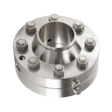
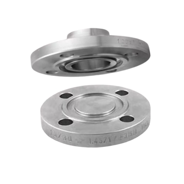
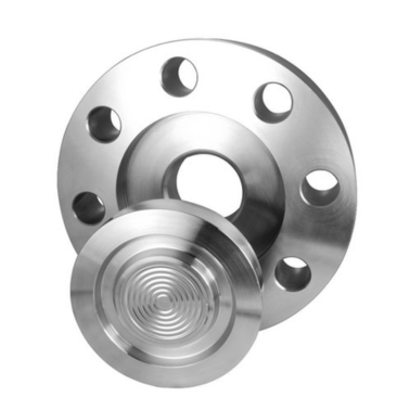
RTJ flanges commonly use oval, octagonal, or spiral wound gaskets, which fit into the grooves of the flanges for a tight seal under high pressure and temperature.
The flange faces have grooves that house a gasket. When the flange bolts are tightened, the gasket is compressed, creating a secure and leak-tight seal between the flange faces, even under extreme pressure conditions.
RTJ flanges differ in their sealing mechanism. Unlike flat face or raised face flanges, which use non-metallic gaskets, RTJ flanges rely on a metallic ring gasket that fits into a groove, providing a more robust seal for high-pressure and high-temperature environments.