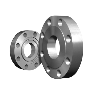
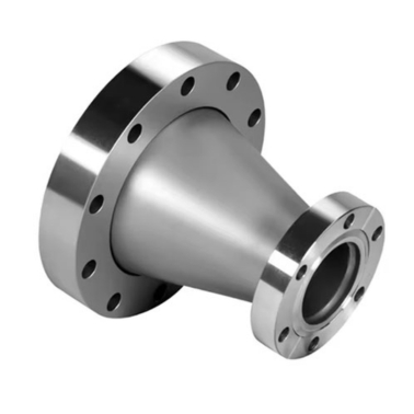
Industrial Pipe Flange Manufacturers |ASME B16.5, B 16.47 Series A & B, B16.48, BS4504, BS 10, EN-1092
ASME/ANSI B16.5 and B16.47 are key standards for pipe flanges and flanged fittings used in various industries. ASME/ANSI B16.5 covers pipe flanges and flanged fittings from 1/2" to 24" nominal pipe sizes for classes ranging from 150 to 2500. These flanges are widely used for connecting pipes, valves, pumps, and other equipment in industries like oil and gas, petrochemicals, and power plants.
ASME/ANSI B16.47, on the other hand, applies to larger-diameter flanges ranging from 26" to 60" and is divided into two series: Series A (formerly MSS SP-44) for higher strength and heavier applications, and Series B (formerly API 605) for lighter and more compact designs. Both standards ensure reliability, safety, and compatibility in high-pressure and high-temperature applications.
Ample Alloys is a leading manufacturer and supplier of high-quality industrial flanges, catering to diverse industries worldwide. With a focus on precision and durability, the company offers a comprehensive range of flanges, including ASME, ANSI, DIN, and custom designs, crafted from premium materials such as carbon steel, stainless steel, and alloys. Known for its commitment to excellence, Ample Alloys ensures all products meet stringent quality standards, providing reliable solutions for oil and gas, petrochemical, power generation, and construction industries.
ASME Flange, ANSI Flange, DIN Flange, EN 1092-1 Flange, Stainless Steel Flange, Carbon Steel Flange, Alloy Steel Flange, High-Pressure Flange, Customized Flange, Forged Flange, Large-Diameter Flanges
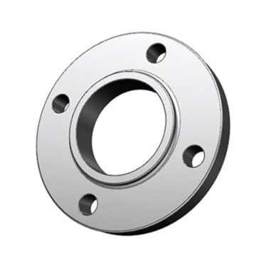
ASME/ANSI B16.5 Flange
Size Range
15mm ( 1/2" NPS ) up to 600mm ( 24" NPS ), For 2500# in sizes from NPS 1/2 to NPS 12
Flange Face Type
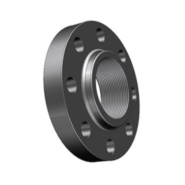
FF—Flat Face, RF—Raised Face, FM—Female Face, M—Male Face, T—Tongue Face, G—Groove Face, RJ—Ring Joint.
Stainless Steel
ASTM A182 F 304, 304L, 304H, 316, 316L, 316H, 317, 317L, 321, 321H, 310, 310S, 347, 904L, etc.
Standards / Dimension
ANSI/ASME B16.5, B 16.47 Series A & B, B16.48, BS4504, BS 10, EN-1092, DIN
Carbon Steel
ASTM A105/A105N (SA105N), LTCS A350 LF2, A694
Alloy Steel
ASTM A182 / SA182 - F1 / F5 / F9 / F11 / F12 / F22 / F91
Pressure Class
150#, 300#, 600#, 900#, 1500#, 2500#, PN6, PN10, PN16, PN25, PN40, PN64.
Duplex & Super Duplex
ASTM A182 / ASME SA182 - S31803, S32205, 2205, S32750, S32760, S32950, 2507.
MTC
EN 10204 3.2 and EN 10204 3.1, Test Certificates certifying NACE MR0175, NACE MR0103
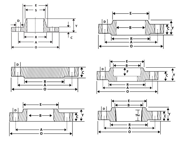
| Nominal Pipe Size |
Flange Dia ‘O’ |
Dia of Bolt Circle ‘A’ |
Dia of Bolt Holes ‘D’ |
No. of Holes |
Thickness of Flange ‘C’ |
Diameter at Weld Bevel | Dia of Hub ‘E’ |
Length Through Hub | Bore ‘B’ | Dia of R/F R |
Depth of Socket F |
Length of Threading |
||||
| S/O & S/W Y |
W/N Y |
L/J Y |
S/O & S/W B |
L/J B |
||||||||||||
| 1/2” | 15 | 88.9 | 60.3 | 15.9 | 4 | 11.1 | 21.3 | 30.2 | 15.9 | 47.6 | 15.9 | 22.3 | 22.9 | 34.9 | 9.5 | 15.9 |
| 3/4” | 20 | 98.4 | 69.8 | 15.9 | 4 | 12.7 | 26.7 | 38.1 | 15.9 | 52.4 | 15.9 | 27.7 | 28.2 | 42.9 | 11.1 | 15.9 |
| 1” | 25 | 107.9 | 79.4 | 15.9 | 4 | 14.3 | 33.5 | 49.2 | 17.5 | 55.6 | 17.5 | 34.5 | 35.0 | 50.8 | 12.7 | 17.5 |
| 1 ¼” | 32 | 117.5 | 88.9 | 15.9 | 4 | 15.9 | 42.2 | 58.7 | 20.6 | 57.1 | 20.6 | 43.2 | 43.7 | 63.5 | 14.3 | 20.6 |
| 1 ½” | 40 | 127.0 | 98.4 | 15.9 | 4 | 17.5 | 48.3 | 65.1 | 22.2 | 61.9 | 22.2 | 49.5 | 50.0 | 73.0 | 15.9 | 22.2 |
| 2” | 50 | 152.4 | 120.6 | 19.0 | 4 | 19.0 | 60.4 | 77.8 | 25.4 | 63.5 | 25.4 | 62.0 | 62.5 | 92.1 | 17.5 | 25.4 |
| 2 ½” | 65 | 177.8 | 139.7 | 19.0 | 4 | 22.2 | 73.1 | 90.5 | 28.6 | 69.8 | 28.6 | 74.7 | 75.4 | 104.8 | 19.0 | 28.6 |
| 3” | 80 | 190.5 | 152.4 | 19.0 | 4 | 23.8 | 88.9 | 107.9 | 30.2 | 69.8 | 30.2 | 90.7 | 91.4 | 127.0 | 20.6 | 30.2 |
| 3 ½” | 90 | 216.0 | 177.8 | 19.0 | 8 | 23.8 | 101.6 | 122.2 | 31.7 | 71.4 | 31.7 | 103.4 | 104.1 | 140.0 | 20.6 | 31.7 |
| 4” | 100 | 228.6 | 190.5 | 19.0 | 8 | 23.8 | 114.3 | 134.9 | 33.3 | 76.2 | 33.3 | 116.1 | 116.8 | 157.2 | 23.8 | 33.3 |
| 5” | 125 | 254.0 | 215.9 | 22.2 | 8 | 23.8 | 141.2 | 163.5 | 36.5 | 88.9 | 36.5 | 143.8 | 144.5 | 185.7 | 23.8 | 36.5 |
| 6” | 150 | 279.4 | 241.3 | 22.2 | 8 | 25.4 | 168.4 | 192.1 | 39.7 | 88.9 | 39.7 | 170.7 | 171.4 | 215.9 | 27.0 | 39.7 |
| 8” | 200 | 342.9 | 298.4 | 22.2 | 8 | 28.6 | 219.2 | 246.1 | 44.4 | 101.6 | 44.4 | 221.5 | 222.2 | 269.9 | 31.7 | 44.4 |
| 10” | 250 | 406.4 | 361.9 | 25.4 | 12 | 30.2 | 273.0 | 304.8 | 49.2 | 101.6 | 49.2 | 276.3 | 277.4 | 323.8 | 33.3 | 49.2 |
| 12” | 300 | 482.6 | 431.8 | 25.4 | 12 | 31.8 | 323.8 | 365.1 | 55.6 | 114.3 | 55.6 | 327.1 | 328.2 | 381.0 | 39.7 | 55.6 |
| 14” | 350 | 533.4 | 476.2 | 28.6 | 12 | 34.9 | 355.6 | 400.0 | 57.1 | 127.0 | 79.4 | 359.1 | 360.2 | 412.7 | 41.3 | 57.1 |
| 16” | 400 | 596.9 | 539.7 | 28.6 | 16 | 36.5 | 406.4 | 457.2 | 63.5 | 127.0 | 87.3 | 410.5 | 411.2 | 469.9 | 44.4 | 63.5 |
| 18” | 450 | 635.0 | 577.8 | 31.7 | 16 | 39.7 | 457.2 | 504.8 | 68.3 | 139.7 | 96.8 | 461.8 | 462.3 | 533.4 | 49.2 | 68.3 |
| 20” | 500 | 698.5 | 635.0 | 31.7 | 20 | 42.9 | 508.0 | 558.8 | 73.0 | 144.5 | 103.2 | 513.1 | 514.3 | 584.2 | 54.0 | 73.0 |
| 24” | 600 | 812.8 | 749.3 | 34.9 | 20 | 47.6 | 609.6 | 663.6 | 82.5 | 152.4 | 111.1 | 615.9 | 615.9 | 692.1 | 63.5 | 82.5 |
| ANSI B 16.5 DIMENSIONS OF CLASS 300 FLANGES in mm | ||||||||||||||||
| Nominal Pipe Size |
Flange Dia ‘O’ |
Dia of Bolt Circle ‘A’ |
Dia of Bolt Holes ‘D’ |
No. of Holes |
Thickness of Flange ‘C’ |
Diameter at Weld Bevel | Dia of Hub ‘E’ |
Length Through Hub | Bore ‘B’ | Dia of R/F R |
Depth of Socket F |
Length of Threading |
||||
| S/O & S/W Y |
W/N Y |
L/J Y |
S/O & S/W B |
L/J B |
||||||||||||
| 1/2” | 15 | 95.2 | 66.7 | 15.9 | 4 | 14.3 | 21.3 | 38.1 | 22.2 | 52.4 | 22.2 | 22.3 | 22.9 | 34.9 | 9.5 | 15.9 |
| 3/4” | 20 | 117.5 | 82.5 | 19.0 | 4 | 15.9 | 26.7 | 47.6 | 25.4 | 57.1 | 25.4 | 27.7 | 28.2 | 42.9 | 11.1 | 15.9 |
| 1” | 25 | 123.8 | 88.9 | 19.0 | 4 | 17.5 | 33.5 | 54.0 | 27.0 | 61.9 | 27.0 | 34.5 | 35.0 | 50.8 | 12.7 | 17.5 |
| 1 ¼” | 32 | 133.3 | 98.4 | 19.0 | 4 | 19.0 | 42.2 | 63.5 | 27.0 | 65.1 | 27.0 | 43.2 | 43.7 | 63.5 | 14.3 | 20.6 |
| 1 ½” | 40 | 155.6 | 114.3 | 22.2 | 4 | 20.6 | 48.3 | 69.8 | 30.2 | 68.3 | 30.2 | 49.5 | 50.0 | 73.0 | 15.9 | 22.2 |
| 2” | 50 | 165.1 | 127.0 | 19.0 | 8 | 22.2 | 60.4 | 84.1 | 33.3 | 69.8 | 33.3 | 62.0 | 62.5 | 92.1 | 17.5 | 25.4 |
| 2 ½” | 65 | 190.5 | 149.2 | 22.2 | 8 | 25.4 | 73.1 | 100.0 | 38.1 | 76.2 | 38.1 | 74.7 | 75.4 | 104.8 | 19.0 | 28.6 |
| 3” | 80 | 209.5 | 168.3 | 22.2 | 8 | 28.6 | 88.9 | 117.5 | 42.9 | 79.4 | 42.9 | 90.7 | 91.4 | 127.0 | 20.6 | 30.2 |
| 3 ½” | 90 | 228.5 | 184.2 | 22.2 | 8 | 30.2 | 101.6 | 133.4 | 44.5 | 81.0 | 44.5 | 103.4 | 104.1 | 140.0 | 20.6 | 31.7 |
| 4” | 100 | 254.0 | 200.0 | 22.2 | 8 | 31.8 | 114.3 | 146.0 | 47.6 | 85.7 | 47.6 | 116.1 | 116.8 | 157.2 | 23.8 | 33.3 |
| 5” | 125 | 279.4 | 234.9 | 22.2 | 8 | 34.9 | 141.2 | 177.8 | 50.8 | 98.4 | 50.8 | 143.8 | 144.5 | 185.7 | – | 36.5 |
| 6” | 150 | 317.5 | 269.9 | 22.2 | 12 | 36.5 | 168.4 | 206.4 | 52.4 | 98.4 | 52.4 | 170.7 | 171.4 | 215.9 | – | 39.7 |
| 8” | 200 | 381.0 | 330.2 | 25.4 | 12 | 41.3 | 219.2 | 260.3 | 61.9 | 111.1 | 61.9 | 221.5 | 222.2 | 269.9 | – | 44.4 |
| 10” | 250 | 444.5 | 387.3 | 28.6 | 16 | 47.6 | 273.0 | 320.7 | 66.7 | 117.5 | 95.2 | 276.3 | 277.4 | 323.8 | – | 49.2 |
| 12” | 300 | 520.7 | 450.8 | 31.7 | 16 | 50.8 | 323.8 | 374.6 | 73.0 | 130.2 | 101.6 | 327.1 | 328.2 | 381.0 | – | 55.6 |
| 14” | 350 | 584.2 | 514.3 | 31.7 | 20 | 54.0 | 355.6 | 425.4 | 76.2 | 142.9 | 111.1 | 359.1 | 360.2 | 412.7 | – | 57.1 |
| 16” | 400 | 647.7 | 571.5 | 34.9 | 20 | 57.2 | 406.4 | 482.6 | 82.5 | 146.0 | 120.6 | 410.5 | 411.2 | 469.9 | – | 63.5 |
| 18” | 450 | 711.2 | 628.5 | 34.9 | 24 | 60.3 | 457.2 | 533.4 | 88.9 | 158.7 | 130.2 | 461.8 | 462.3 | 533.4 | – | 68.3 |
| 20” | 500 | 774.7 | 685.8 | 34.9 | 24 | 63.5 | 508.0 | 587.4 | 95.2 | 161.9 | 139.7 | 513.1 | 514.3 | 584.2 | – | 73.0 |
| 24” | 600 | 914.4 | 812.8 | 41.3 | 24 | 69.8 | 609.6 | 701.7 | 106.4 | 168.3 | 152.4 | 615.9 | 615.9 | 692.1 | – | 82.5 |
| ANSI B 16.5 Class 600 flange dimensions in mm | ||||||||||||||||
| Nominal Pipe Size |
Flange Dia ‘O’ |
Dia of Bolt Circle ‘A’ |
Dia of Bolt Holes ‘D’ |
No. of Holes |
Thickness of Flange ‘C’ |
Diameter at Weld Bevel | Dia of Hub ‘E’ |
Length Through Hub | Bore ‘B’ | Dia of R/F R |
Depth of Socket F |
Length of Threading |
||||
| S/O & S/W Y |
W/N Y |
L/J Y |
S/O & S/W B |
L/J B |
||||||||||||
| 1/2” | 15 | 95.2 | 66.7 | 15.9 | 4 | 14.3 | 21.3 | 38.1 | 22.2 | 52.4 | 22.2 | 22.3 | 22.9 | 34.9 | 9.5 | 15.9 |
| 3/4” | 20 | 117.5 | 82.5 | 19.0 | 4 | 15.9 | 26.7 | 47.6 | 25.4 | 57.1 | 25.4 | 27.7 | 28.2 | 42.9 | 11.1 | 15.9 |
| 1” | 25 | 123.8 | 88.9 | 19.0 | 4 | 17.5 | 33.5 | 54.0 | 27.0 | 61.9 | 27.0 | 34.5 | 35.0 | 50.8 | 12.7 | 17.5 |
| 1 ¼” | 32 | 133.3 | 98.4 | 19.0 | 4 | 20.6 | 42.2 | 63.5 | 28.6 | 66.7 | 28.6 | 43.2 | 43.7 | 63.5 | 14.3 | 20.6 |
| 1 ½” | 40 | 155.6 | 114.3 | 22.2 | 4 | 22.2 | 48.3 | 69.8 | 31.7 | 69.8 | 31.7 | 49.5 | 50.0 | 73.0 | 15.9 | 22.2 |
| 2” | 50 | 165.1 | 127.0 | 19.0 | 8 | 25.4 | 60.4 | 84.1 | 36.5 | 73.0 | 36.5 | 62.0 | 62.5 | 92.1 | 17.5 | 25.4 |
| 2 ½” | 65 | 190.5 | 149.2 | 22.2 | 8 | 28.6 | 73.1 | 100.0 | 41.3 | 79.4 | 41.3 | 74.7 | 75.4 | 104.8 | 19.0 | 28.6 |
| 3” | 80 | 209.5 | 168.3 | 22.2 | 8 | 31.8 | 88.9 | 117.5 | 46.0 | 82.5 | 46.0 | 90.7 | 91.4 | 127.0 | – | 30.2 |
| 3 ½” | 90 | 228.5 | 184.2 | 22.2 | 8 | 34.9 | 101.6 | 133.4 | 49.3 | 85.7 | 49.3 | 103.4 | 104.1 | 140.0 | – | 31.7 |
| 4” | 100 | 273.0 | 215.9 | 25.4 | 8 | 38.1 | 114.3 | 152.4 | 54.0 | 101.6 | 54.0 | 116.1 | 116.8 | 157.2 | – | 33.3 |
| 5” | 125 | 330.2 | 266.7 | 28.6 | 8 | 44.4 | 141.2 | 188.9 | 60.3 | 114.3 | 60.3 | 143.8 | 144.5 | 185.7 | – | 36.5 |
| 6” | 150 | 355.6 | 292.1 | 28.6 | 12 | 47.6 | 168.4 | 222.2 | 66.7 | 117.5 | 66.7 | 170.7 | 171.4 | 215.9 | – | 39.7 |
| 8” | 200 | 419.1 | 349.2 | 31.7 | 12 | 55.6 | 219.2 | 273.0 | 76.2 | 133.3 | 76.2 | 221.5 | 222.2 | 269.9 | – | 44.4 |
| 10” | 250 | 508.0 | 431.8 | 34.9 | 16 | 63.5 | 273.0 | 342.9 | 85.7 | 152.4 | 111.2 | 276.3 | 277.4 | 323.8 | – | 49.2 |
| 12” | 300 | 558.8 | 488.9 | 34.9 | 20 | 66.7 | 323.8 | 400.0 | 92.1 | 155.6 | 117.3 | 327.1 | 328.2 | 381.0 | – | 55.6 |
| 14” | 350 | 603.2 | 527.0 | 38.1 | 20 | 69.9 | 355.6 | 431.8 | 93.7 | 165.1 | 127.0 | 359.1 | 360.2 | 412.7 | – | 57.1 |
| 16” | 400 | 685.8 | 603.2 | 41.3 | 20 | 76.2 | 406.4 | 495.3 | 106.4 | 177.8 | 139.7 | 410.5 | 411.2 | 469.9 | – | 63.5 |
| 18” | 450 | 742.9 | 654.0 | 44.4 | 24 | 82.6 | 457.2 | 546.1 | 117.5 | 184.1 | 152.4 | 461.8 | 462.3 | 533.4 | – | 68.3 |
| 20” | 500 | 812.8 | 723.9 | 44.4 | 24 | 88.9 | 508.0 | 609.6 | 127.0 | 190.5 | 165.1 | 513.1 | 514.3 | 584.2 | – | 73.0 |
| 24” | 600 | 939.8 | 838.2 | 50.8 | 24 | 101.6 | 609.6 | 717.5 | 139.7 | 203.2 | 184.1 | 615.9 | 615.9 | 692.1 | – | 82.5 |
| ANSI B 16.5 Class 900 flange dimensions in mm | ||||||||||||||||
| Nominal Pipe Size |
Flange Dia ‘O’ |
Dia of Bolt Circle ‘A’ |
Dia of Bolt Holes ‘D’ |
No. of Holes |
Thickness of Flange ‘C’ |
Diameter at Weld Bevel | Dia of Hub ‘E’ |
Length Through Hub | Bore ‘B’ | Dia of R/F R |
Depth of Socket F |
Length of Threading |
||||
| S/O & S/W Y |
W/N Y |
L/J Y |
S/O & S/W B |
L/J B |
||||||||||||
| 1/2” | 15 | 95.2 | 66.7 | 15.9 | 4 | 14.3 | 21.3 | 38.1 | 22.2 | 52.4 | 22.2 | 22.3 | 22.9 | 34.9 | 9.5 | 15.9 |
| 3/4” | 20 | 117.5 | 82.5 | 19.0 | 4 | 15.9 | 26.7 | 47.6 | 25.4 | 57.1 | 25.4 | 27.7 | 28.2 | 42.9 | 11.1 | 15.9 |
| 1” | 25 | 123.8 | 88.9 | 19.0 | 4 | 17.5 | 33.5 | 54.0 | 27.0 | 61.9 | 27.0 | 34.5 | 35.0 | 50.8 | 12.7 | 17.5 |
| 1 ¼” | 32 | 133.3 | 98.4 | 19.0 | 4 | 20.6 | 42.2 | 63.5 | 28.6 | 66.7 | 28.6 | 43.2 | 43.7 | 63.5 | 14.3 | 20.6 |
| 1 ½” | 40 | 155.6 | 114.3 | 22.2 | 4 | 22.2 | 48.3 | 69.8 | 31.7 | 69.8 | 31.7 | 49.5 | 50.0 | 73.0 | 15.9 | 22.2 |
| 2” | 50 | 165.1 | 127.0 | 19.0 | 8 | 25.4 | 60.4 | 84.1 | 36.5 | 73.0 | 36.5 | 62.0 | 62.5 | 92.1 | 17.5 | 25.4 |
| 2 ½” | 65 | 190.5 | 149.2 | 22.2 | 8 | 28.6 | 73.1 | 100.0 | 41.3 | 79.4 | 41.3 | 74.7 | 75.4 | 104.8 | 19.0 | 28.6 |
| 3” | 80 | 209.5 | 168.3 | 22.2 | 8 | 31.8 | 88.9 | 117.5 | 46.0 | 82.5 | 46.0 | 90.7 | 91.4 | 127.0 | – | 30.2 |
| 3 ½” | 90 | 228.5 | 184.2 | 22.2 | 8 | 34.9 | 101.6 | 133.4 | 49.3 | 85.7 | 49.3 | 103.4 | 104.1 | 140.0 | – | 31.7 |
| 4” | 100 | 273.0 | 215.9 | 25.4 | 8 | 38.1 | 114.3 | 152.4 | 54.0 | 101.6 | 54.0 | 116.1 | 116.8 | 157.2 | – | 33.3 |
| 5” | 125 | 330.2 | 266.7 | 28.6 | 8 | 44.4 | 141.2 | 188.9 | 60.3 | 114.3 | 60.3 | 143.8 | 144.5 | 185.7 | – | 36.5 |
| 6” | 150 | 355.6 | 292.1 | 28.6 | 12 | 47.6 | 168.4 | 222.2 | 66.7 | 117.5 | 66.7 | 170.7 | 171.4 | 215.9 | – | 39.7 |
| 8” | 200 | 419.1 | 349.2 | 31.7 | 12 | 55.6 | 219.2 | 273.0 | 76.2 | 133.3 | 76.2 | 221.5 | 222.2 | 269.9 | – | 44.4 |
| 10” | 250 | 508.0 | 431.8 | 34.9 | 16 | 63.5 | 273.0 | 342.9 | 85.7 | 152.4 | 111.2 | 276.3 | 277.4 | 323.8 | – | 49.2 |
| 12” | 300 | 558.8 | 488.9 | 34.9 | 20 | 66.7 | 323.8 | 400.0 | 92.1 | 155.6 | 117.3 | 327.1 | 328.2 | 381.0 | – | 55.6 |
| 14” | 350 | 603.2 | 527.0 | 38.1 | 20 | 69.9 | 355.6 | 431.8 | 93.7 | 165.1 | 127.0 | 359.1 | 360.2 | 412.7 | – | 57.1 |
| 16” | 400 | 685.8 | 603.2 | 41.3 | 20 | 76.2 | 406.4 | 495.3 | 106.4 | 177.8 | 139.7 | 410.5 | 411.2 | 469.9 | – | 63.5 |
| 18” | 450 | 742.9 | 654.0 | 44.4 | 24 | 82.6 | 457.2 | 546.1 | 117.5 | 184.1 | 152.4 | 461.8 | 462.3 | 533.4 | – | 68.3 |
| 20” | 500 | 812.8 | 723.9 | 44.4 | 24 | 88.9 | 508.0 | 609.6 | 127.0 | 190.5 | 165.1 | 513.1 | 514.3 | 584.2 | – | 73.0 |
| 24” | 600 | 939.8 | 838.2 | 50.8 | 24 | 101.6 | 609.6 | 717.5 | 139.7 | 203.2 | 184.1 | 615.9 | 615.9 | 692.1 | – | 82.5 |
| ANSI B 16.5 Class 1500 flange dimensions in mm | ||||||||||||||||
| Nominal Pipe Size |
Flange Dia ‘O’ |
Dia of Bolt Circle ‘A’ |
Dia of Bolt Holes ‘D’ |
No. of Holes |
Thickness of Flange ‘C’ |
Diameter at Weld Bevel | Dia of Hub ‘E’ |
Length Through Hub | Bore ‘B’ | Dia of R/F R |
Depth of Socket F |
Length of Threading |
||||
| S/O & S/W Y |
W/N Y |
L/J Y |
S/O & S/W B |
L/J B |
||||||||||||
| 1/2” | 15 | 120.6 | 82.5 | 22.2 | 4 | 22.2 | 21.3 | 38.1 | 31.7 | 60.3 | 31.7 | 22.3 | 22.9 | 34.9 | 9.5 | 22.2 |
| 3/4” | 20 | 130.2 | 88.9 | 22.2 | 4 | 25.4 | 26.7 | 44.4 | 34.9 | 69.8 | 34.9 | 27.7 | 28.2 | 42.9 | 11.1 | 25.4 |
| 1” | 25 | 149.2 | 101.6 | 25.4 | 4 | 28.6 | 33.5 | 52.4 | 41.3 | 73.0 | 41.3 | 34.5 | 35.0 | 50.8 | 12.7 | 28.6 |
| 1 ¼” | 32 | 158.7 | 111.1 | 25.4 | 4 | 28.6 | 42.2 | 63.5 | 41.3 | 73.0 | 41.3 | 43.2 | 43.7 | 63.5 | 14.3 | 30.2 |
| 1 ½” | 40 | 177.8 | 123.8 | 28.6 | 4 | 31.8 | 48.3 | 69.8 | 44.4 | 82.5 | 44.4 | 49.5 | 50.0 | 73.0 | 15.9 | 31.7 |
| 2” | 50 | 215.9 | 165.1 | 25.4 | 8 | 38.1 | 60.4 | 104.8 | 57.1 | 101.6 | 57.1 | 62.0 | 62.5 | 92.1 | 17.5 | 38.1 |
| 2 ½” | 65 | 244.5 | 190.5 | 28.6 | 8 | 41.3 | 73.1 | 123.8 | 63.5 | 123.8 | 63.5 | 74.7 | 75.4 | 104.8 | 19.0 | 47.6 |
| 3” | 80 | 266.7 | 203.2 | 31.7 | 8 | 47.6 | 88.9 | 133.3 | 73.0 | 117.5 | 73.0 | 90.7 | 91.4 | 127.0 | – | 50.8 |
| 4” | 100 | 311.1 | 241.3 | 34.9 | 8 | 54.0 | 114.3 | 161.9 | 90.5 | 123.0 | 90.5 | 116.1 | 116.8 | 157.2 | – | 57.1 |
| 5” | 125 | 374.6 | 292.1 | 41.3 | 8 | 73.0 | 141.2 | 196.8 | 104.8 | 155.6 | 104.8 | 143.8 | 144.5 | 185.7 | – | 63.5 |
| 6” | 150 | 393.7 | 317.5 | 38.1 | 12 | 82.6 | 168.4 | 228.6 | 119.1 | 171.4 | 119.1 | 170.7 | 171.4 | 215.9 | – | 69.8 |
| 8” | 200 | 482.6 | 393.7 | 44.4 | 12 | 92.1 | 219.2 | 292.1 | 142.9 | 212.7 | 142.8 | 221.5 | 222.2 | 269.9 | – | 76.2 |
| 10” | 250 | 584.2 | 482.6 | 50.8 | 12 | 107.9 | 273.0 | 368.3 | 158.7 | 254.0 | 177.8 | 276.3 | 277.4 | 323.8 | – | 84.1 |
| 12” | 300 | 673.1 | 571.5 | 54.0 | 16 | 123.8 | 323.8 | 450.8 | 181.0 | 282.5 | 219.1 | 327.1 | 328.2 | 381.0 | – | 92.1 |
| 14” | 350 | 749.5 | 635.0 | 60.5 | 16 | 133.4 | 355.6 | 495.3 | – | 298.5 | 241.3 | 359.1 | 360.2 | 412.7 | – | – |
| 16” | 400 | 825.5 | 704.9 | 66.5 | 16 | 146.1 | 406.4 | 552.5 | – | 311.2 | 260.4 | 410.5 | 411.2 | 469.9 | – | – |
| 18” | 450 | 914.5 | 774.7 | 73.5 | 16 | 162.0 | 457.2 | 596.9 | – | 327.0 | 276.2 | 461.8 | 462.3 | 533.4 | – | – |
| 20” | 500 | 984.0 | 831.9 | 79.5 | 16 | 177.8 | 508.0 | 641.4 | – | 355.6 | 292.1 | 513.1 | 514.3 | 584.2 | – | – |
| 24” | 600 | 1168.5 | 990.6 | 92.0 | 16 | 203.2 | 609.6 | 762.0 | – | 406.4 | 330.2 | 615.9 | 615.9 | 692.1 | – | – |
| ANSI B 16.5 Class 2500 flange dimensions in mm | ||||||||||||||||
| Nominal Pipe Size |
Flange Dia ‘O’ |
Dia of Bolt Circle ‘A’ |
Dia of Bolt Holes ‘D’ |
No. of Holes |
Thickness of Flange ‘C’ |
Diameter at Weld Bevel | Dia of Hub ‘E’ |
Length Through Hub | Bore ‘B’ | Dia of R/F R |
Depth of Socket F |
Length of Threading |
||||
| S/O & S/W Y |
W/N Y |
L/J Y |
S/O & S/W B |
L/J B |
||||||||||||
| 1/2” | 15 | 133.3 | 88.9 | 22.2 | 4 | 30.2 | 21.3 | 42.9 | 39.7 | 73.3 | 39.7 | 22.3 | 22.9 | 34.9 | – | 28.6 |
| 3/4” | 20 | 139.7 | 95.2 | 22.2 | 4 | 31.7 | 26.7 | 50.8 | 42.9 | 79.4 | 42.9 | 27.7 | 28.2 | 42.9 | – | 31.7 |
| 1” | 25 | 158.7 | 107.9 | 25.4 | 4 | 34.9 | 33.5 | 57.1 | 47.7 | 88.9 | 47.7 | 34.5 | 35.0 | 50.8 | – | 34.9 |
| 1 ¼” | 32 | 184.1 | 130.2 | 28.6 | 4 | 38.1 | 42.2 | 73.0 | 52.4 | 95.2 | 52.4 | 43.2 | 43.7 | 63.5 | – | 38.1 |
| 1 ½” | 40 | 203.2 | 146.0 | 31.7 | 4 | 44.4 | 48.3 | 79.4 | 60.3 | 111.1 | 60.3 | 49.5 | 50.0 | 73.0 | – | 44.4 |
| 2” | 50 | 234.9 | 171.4 | 28.6 | 8 | 50.8 | 60.4 | 95.2 | 69.8 | 127.0 | 69.8 | 62.0 | 62.5 | 92.1 | – | 50.8 |
| 2 ½” | 65 | 266.7 | 196.8 | 31.7 | 8 | 57.1 | 73.1 | 114.3 | 79.4 | 142.9 | 79.4 | 74.7 | 75.4 | 104.8 | – | 57.1 |
| 3” | 80 | 304.8 | 228.6 | 34.9 | 8 | 66.7 | 88.9 | 133.3 | 92.1 | 168.3 | 92.1 | 90.7 | 91.4 | 127.0 | – | 63.5 |
| 4” | 100 | 355.6 | 273.0 | 41.3 | 8 | 76.2 | 114.3 | 165.1 | 107.9 | 190.5 | 107.9 | 116.1 | 116.8 | 157.2 | – | 69.8 |
| 5” | 125 | 419.1 | 323.8 | 47.6 | 8 | 92.1 | 141.2 | 203.2 | 130.0 | 128.6 | 130.0 | 143.8 | 144.5 | 185.7 | – | 76.2 |
| 6” | 150 | 482.6 | 368.3 | 54.0 | 8 | 107.9 | 168.4 | 234.9 | 152.4 | 273.0 | 152.4 | 170.7 | 171.4 | 215.9 | – | 82.5 |
| 8” | 200 | 552.4 | 438.1 | 54.0 | 12 | 127.0 | 219.2 | 304.8 | 177.8 | 317.5 | 177.8 | 221.5 | 222.2 | 269.9 | – | 95.2 |
| 10” | 250 | 673.1 | 539.7 | 66.7 | 12 | 165.1 | 273.0 | 374.6 | 228.6 | 419.1 | 228.6 | 276.3 | 277.4 | 323.8 | – | 107.9 |
| 12” | 300 | 762.0 | 619.1 | 73.0 | 12 | 184.1 | 323.8 | 441.3 | 254.0 | 463.5 | 254.0 | 327.1 | 328.2 | 381.0 | – | 120.6 |
Flange Standards
These Pipe Flange standards define dimensions, material requirements, pressure ratings, and manufacturing tolerances, ensuring interchangeability, safety, and reliability.
- ASME/ANSI Standards (American):
- ASME B16.5 – Pipe Flanges and Flanged Fittings (NPS 1/2" to 24").
- ASME B16.47 – Large Diameter Steel Flanges (Series A & B, NPS 26" to 60").
- ASME B16.36 – Orifice Flanges.
- ASME B16.48 – Line Blanks (Spectacle, Spade, and Spacer Flanges).
- ANSI B16.1 – Cast Iron Flanges and Flanged Fittings.
- ANSI B16.42 – Ductile Iron Pipe Flanges and Flanged Fittings.
- ISO Standards (International)
- ISO 7005-1 – Steel Flanges for General Applications.
- ISO 7005-2 – Cast Iron Flanges.
- ISO 7005-3 – Copper Alloy Flanges.
- EN Standards (European)
- EN 1092-1 – Steel Flanges.
- EN 1092-2 – Cast Iron Flanges.
- EN 1092-3 – Copper Alloy Flanges.
- EN 1092-4 – Aluminium Alloy Flanges.
- DIN Standards (German)
- DIN 2527 – Blind Flanges.
- DIN 2576 – Slip-On Flanges (PN 10).
- DIN 2633 – Weld Neck Flanges (PN 16).
- DIN 2634 – Weld Neck Flanges (PN 25).
- DIN 2635 – Weld Neck Flanges (PN 40).
- JIS Standards (Japanese)
- JIS B2220 – Steel Pipe Flanges.
- GOST Standards (Russian)
- GOST 12820 – Flat Flanges for Steel Pipe Joints.
- GOST 12821 – Steel Welded Flanges for High-Pressure Applications.
- GOST 33259 – Flange Connections for Industrial Equipment and Pipelines.
- BS Standards (British)
- BS 4504 – Circular Flanges for Pipes, Valves, and Fittings.
- BS 10 – Specification for Flanges and Bolting.
- API Standards (Oil & Gas)
- API 6A – Wellhead and Christmas Tree Equipment Flanges.
- API 605 – Large-Diameter Carbon Steel Flanges (merged into ASME B16.47 Series B).
- AWWA Standards (Waterworks)
- AWWA C207 – Steel Ring Flanges for Waterworks Service.
- MSS Standards (Manufacturer's Standardization Society)
- MSS SP-44 – Steel Pipe Flanges (merged into ASME B16.47 Series A).
- MSS SP-51 – Flanges for Glass-Lined Equipment.
- Material-Specific Standards (ASTM)
- ASTM A105 – Carbon Steel Forged Flanges.
- ASTM A182 – Alloy and Stainless Steel Forged Flanges.
- ASTM A350 – Carbon and Low-Alloy Steel Flanges for Low-Temperature Service.
- ASTM A694 – High-Strength Carbon and Alloy Steel Flanges for High-Pressure Applications.
- Other Regional and Specialized Standards
- KS B1511 – Korean Standard Flanges.
- NF E29-206 – French Standard Flanges.
- SANS 1123 – South African Standard for Steel Flanges.
Why Ample Alloys For Steel Flanges!
We are stands out as a trusted name in the manufacturing and supply of high-quality steel flanges. Choose Ample Alloys for unmatched quality, reliability, and service in steel flanges.
Extensive Product Range
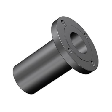
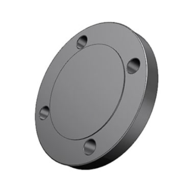
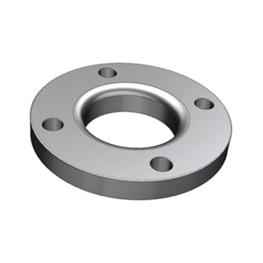
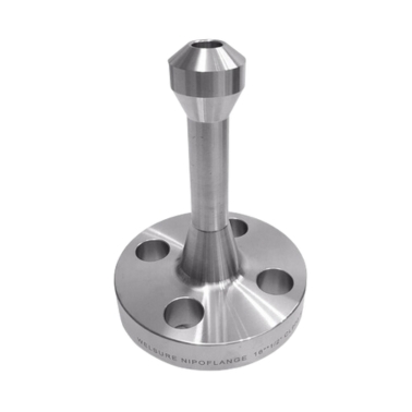
Offering a comprehensive selection of flanges, including Weld Neck, Slip-On, Blind, Threaded, Socket Weld, and Lap Joint Flanges, crafted to meet international standards like ASME, ANSI, DIN, EN, and JIS.
Superior Quality
Committed to excellence, Ample Alloys ensures all products undergo rigorous quality checks to meet stringent industrial requirements for safety, durability, and precision.
Material Versatility
Specializing in carbon steel, stainless steel, and alloy steel flanges, suitable for diverse applications across oil & gas, petrochemical, power generation, and other sectors.
Customization Capabilities
Tailored solutions to match unique project specifications, including custom sizes, materials, and pressure ratings.
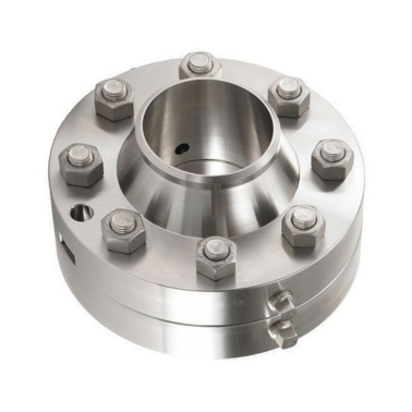
Flanges are connected using bolts and gaskets to ensure a leak-proof seal between the flange faces.
- Oil and Gas
- Petrochemical and Chemical
- Power Generation
- Water Treatment
- Marine and Shipbuilding
- HVAC Systems
- Pipe size and material
- Pressure and temperature requirements
- Flange type and connection style
- Industry standards compliance