Exporter of ANSI/ASME B16.36 Orifice Flange
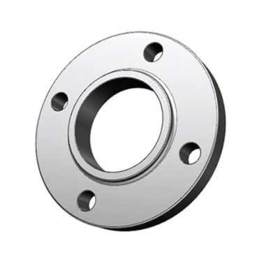
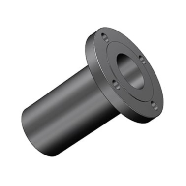
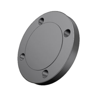
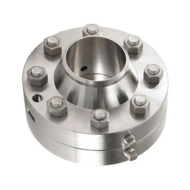
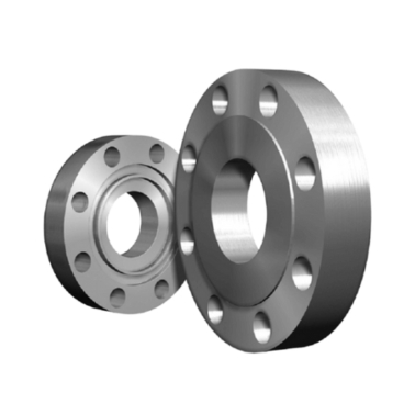
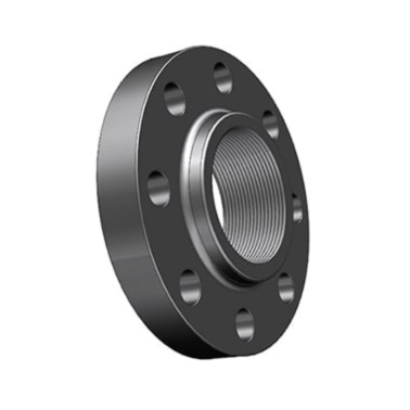
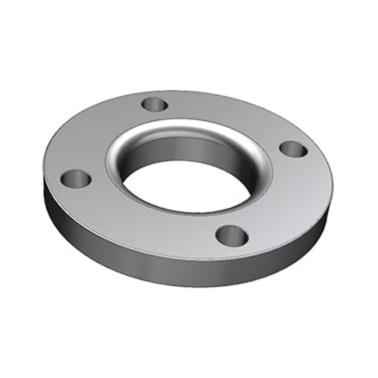
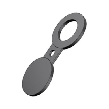
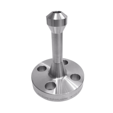
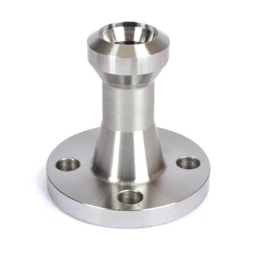
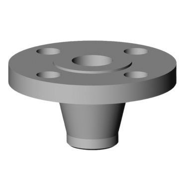
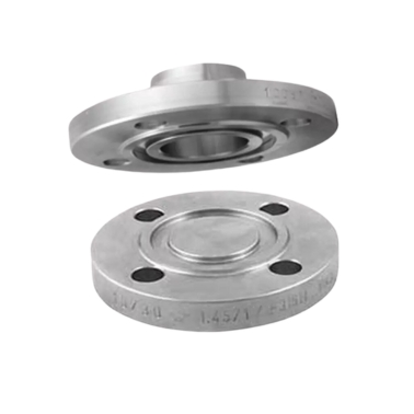
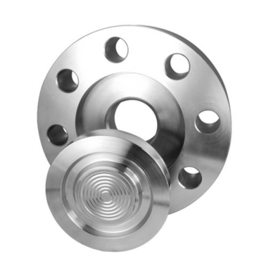
An Orifice Flange is a specialized type of flange used in piping systems to facilitate the installation of an orifice plate for flow measurement applications. Typically used in oil and gas, chemical, and water treatment industries, orifice flanges provide a secure and precise method for measuring the flow rate of liquids or gases. These Orifice flanges are designed with bolt holes to fit the orifice plate, which is installed between the two flanges to create a pressure drop. The orifice plate then measures the differential pressure, which can be used to calculate flow rates. Orifice flanges are often available in various sizes, materials, and pressure ratings to meet the demands of specific applications, and they are designed to meet industry standards like ANSI B16.36. They are essential in applications where accurate flow measurement is critical to maintaining system efficiency and safety.
Ample Alloys is a trusted supplier of high-quality Orifice Flanges, offering exceptional precision and durability. Our orifice flanges are designed and manufactured according to international standards like ANSI B16.36, ensuring reliable performance and consistent results. With a diverse range of materials available, including carbon steel, stainless steel, and alloy steels, we provide customized solutions to meet your specific system requirements. Our commitment to precision, timely delivery, and competitive pricing makes us a preferred choice for clients seeking cost-effective and high-performance orifice flanges. Additionally, our rigorous quality control processes guarantee that each product meets stringent quality standards, ensuring optimal performance and reliability.

Orifice Plate Flange, High Pressure Orifice Flange, Stainless Steel, Carbon Steel, Alloy Steel Orifice Flange, Orifice Flange for Flow Meters, Custom Orifice Flanges, API Orifice Flange, Weld Neck Orifice Flange, Raised Face Orifice Flange
ANSI B16.36 Orifice Flange
Size Range
15mm ( 1/2" NPS ) up to 600mm ( 24" NPS ), For 2500# in sizes from NPS 1/2 to NPS 12
Flange Face Type
FF—Flat Face, RF—Raised Face, FM—Female Face, M—Male Face, T—Tongue Face, G—Groove Face, RJ—Ring Joint.
Stainless Steel
ASTM A182 F 304, 304L, 304H, 316, 316L, 316H, 317, 317L, 321, 321H, 310, 310S, 347, 904L, etc.
Standards / Dimension
ANSI/ASME B16.36, BS4504, BS 10, EN-1092, DIN
Carbon Steel
ASTM A105/A105N (SA105N), LTCS A350 LF2, A694
Alloy Steel
ASTM A182 / SA182 - F1 / F5 / F9 / F11 / F12 / F22 / F91
Pressure Class
150#, 300#, 600#, 900#, 1500#, 2500#, PN6, PN10, PN16, PN25, PN40, PN64.
Duplex & Super Duplex
ASTM A182 / ASME SA182 - S31803, S32205, 2205, S32750, S32760, S32950, 2507.
MTC
EN 10204 3.2 and EN 10204 3.1, Test Certificates certifying NACE MR0175, NACE MR0103
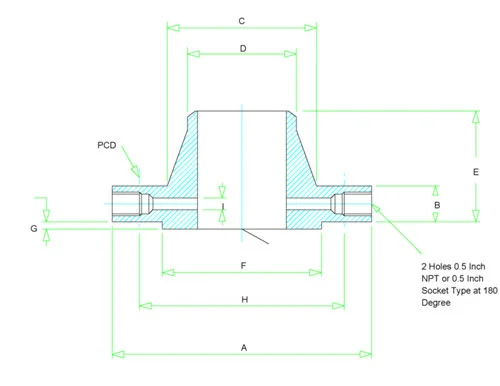
| Size in Inch | Size in mm | Outer Dia. | Flange Thick. | Hub OD | Weld Neck OD | Welding Neck Length | RF Dia. | RF Height | PCD | Orifice Hole dia | No of Bolts | Bolt Size UNC | RF Stud Length | Hole Size | ISO Stud Size | Weight in kg |
|---|---|---|---|---|---|---|---|---|---|---|---|---|---|---|---|---|
| A | B | C | D | E | F | G | H | I | ||||||||
| 1 | 25 | 125 | 36.6 | 54 | 33.4 | 81 | 50.8 | 2 | 88.9 | 6.4 | 4 | 5/8 | 125 | 3/4 | M16 | 4.5 |
| 1 1/2 | 40 | 155 | 36.6 | 70 | 48.3 | 84 | 73 | 2 | 114.3 | 6.4 | 4 | 3/4 | 135 | 7/8 | M20 | 6.5 |
| 2 | 50 | 165 | 36.6 | 84 | 60.3 | 84 | 92.1 | 2 | 127 | 6.4 | 8 | 5/8 | 125 | 3/4 | M16 | 7 |
| 2 1/2 | 65 | 190 | 36.6 | 100 | 73 | 87 | 104.8 | 2 | 149.2 | 6.4 | 8 | 3/4 | 135 | 7/8 | M20 | 7.5 |
| 3 | 80 | 210 | 36.6 | 117 | 88.9 | 87 | 127 | 2 | 168.3 | 9.5 | 8 | 3/4 | 135 | 7/8 | M20 | 9.4 |
| 4 | 100 | 255 | 36.6 | 146 | 114.3 | 90 | 157.2 | 2 | 200 | 12.7 | 8 | 3/4 | 135 | 7/8 | M20 | 13.2 |
| 6 | 150 | 320 | 36.6 | 206 | 168.3 | 98 | 215.9 | 2 | 269.9 | 12.7 | 12 | 3/4 | 135 | 7/8 | M20 | 14.6 |
| 8 | 200 | 380 | 39.7 | 260 | 219.1 | 110 | 269.9 | 2 | 330.2 | 12.7 | 12 | 7/8 | 145 | 1 | M24 | 30 |
| 10 | 250 | 445 | 46.1 | 321 | 273 | 116 | 323.8 | 2 | 387.3 | 12.7 | 16 | 1 | 165 | 1 1/8 | M27 | 41 |
| 12 | 300 | 520 | 49.3 | 375 | 323.8 | 129 | 381 | 2 | 450.8 | 12.7 | 16 | 1 1/8 | 180 | 1 1/4 | M30 | 62 |
| 14 | 350 | 585 | 52.4 | 425 | 355.6 | 141 | 412.8 | 2 | 514.4 | 12.7 | 20 | 1 1/8 | 185 | 1 1/4 | M30 | 84 |
| 16 | 400 | 650 | 55.6 | 483 | 406.4 | 144 | 469.9 | 2 | 571.5 | 12.7 | 20 | 1 1/4 | 195 | 1 3/8 | M33 | 111 |
| 18 | 450 | 710 | 58.8 | 533 | 457 | 157 | 533.4 | 2 | 628.6 | 12.7 | 24 | 1 1/4 | 205 | 1 3/8 | M33 | 138 |
| 20 | 500 | 775 | 62 | 587 | 508 | 160 | 584.2 | 2 | 685.8 | 12.7 | 24 | 1 1/4 | 215 | 1 3/8 | M33 | 171 |
| 24 | 600 | 915 | 68.3 | 702 | 610 | 167 | 692.2 | 2 | 812.8 | 12.7 | 24 | 1 1/2 | 240 | 1 5/8 | M39 | 247 |
| Size in Inch | Size in mm | Outer Dia. | Flange Thick. | Hub OD | Weld Neck OD | Welding Neck Length | RF Dia. | RF Height | PCD | Orifice Hole dia | No of Bolts | Bolt Size UNC | RF Stud Length | Hole Size | ISO Stud Size | Weight in kg |
|---|---|---|---|---|---|---|---|---|---|---|---|---|---|---|---|---|
| A | B | C | D | E | F | G | H | I | ||||||||
| 1 | 25 | 125 | 36.6 | 54 | 33.5 | 81 | 50.8 | 7 | 88.9 | 6.4 | 4 | 5/8 | 125 | 3/4 | M16 | 5.5 |
| 1 1/2 | 40 | 155 | 36.6 | 70 | 48.3 | 84 | 73 | 7 | 114.3 | 6.4 | 4 | 3/4 | 135 | 7/8 | M20 | 7.8 |
| 2 | 50 | 165 | 36.6 | 84 | 60.3 | 84 | 92.1 | 7 | 127 | 6.4 | 8 | 5/8 | 125 | 3/4 | M16 | 8.3 |
| 2 1/2 | 65 | 190 | 36.6 | 100 | 73 | 87 | 104.8 | 7 | 149.2 | 6.4 | 8 | 3/4 | 135 | 7/8 | M20 | 10.8 |
| 3 | 80 | 210 | 36.6 | 117 | 88.9 | 87 | 127 | 7 | 168.3 | 9.5 | 8 | 3/4 | 135 | 7/8 | M20 | 12.6 |
| 4 | 100 | 275 | 38.1 | 152 | 114.3 | 102 | 157.2 | 7 | 215.9 | 12.7 | 8 | 7/8 | 150 | 1 | M24 | 19 |
| 6 | 150 | 355 | 47.7 | 222 | 168.3 | 117 | 215.9 | 7 | 292.1 | 12.7 | 12 | 1 | 180 | 1 1/8 | M27 | 37 |
| 8 | 200 | 420 | 55.6 | 273 | 219.1 | 133 | 269.9 | 7 | 349.2 | 12.7 | 12 | 1 1/8 | 195 | 1 1/4 | M30 | 53 |
| 10 | 250 | 510 | 63.5 | 343 | 273 | 152 | 323.8 | 7 | 431.8 | 12.7 | 16 | 1 1/4 | 220 | 1 3/8 | M33 | 86 |
| 12 | 300 | 560 | 66.7 | 400 | 323.8 | 156 | 381 | 7 | 489 | 12.7 | 20 | 1 1/4 | 230 | 1 3/8 | M33 | 102 |
| 14 | 350 | 605 | 69.9 | 432 | 355.6 | 165 | 412.8 | 7 | 527 | 12.7 | 20 | 1 3/8 | 240 | 1 1/2 | M36 | 150 |
| 16 | 400 | 685 | 76.2 | 495 | 406.4 | 178 | 469.9 | 7 | 603.2 | 12.7 | 20 | 1 1/2 | 260 | 1 5/8 | M39 | 190 |
| 18 | 450 | 745 | 82.6 | 546 | 457.2 | 184 | 533.4 | 7 | 654 | 12.7 | 20 | 1 5/8 | 280 | 1 3/4 | M42 | 240 |
| 20 | 500 | 815 | 88.9 | 610 | 508 | 190 | 584.2 | 7 | 723.9 | 12.7 | 24 | 1 5/8 | 300 | 1 3/4 | M42 | 295 |
| 24 | 600 | 940 | 101.6 | 718 | 609.6 | 203 | 692.2 | 7 | 838.2 | 12.7 | 24 | 1 7/8 | 335 | 2 | M48 | 365 |
| Size in Inch | Size in mm | Outer Dia. | Flange Thick. | Hub OD | Weld Neck OD | Welding Neck Length | RF Dia. | RF Height | PCD | Orifice Hole dia | No of Bolts | Bolt Size UNC | RF Stud Length | Hole Size | ISO Stud Size | Weight in kg |
|---|---|---|---|---|---|---|---|---|---|---|---|---|---|---|---|---|
| A | B | C | D | E | F | G | H | I | ||||||||
| 1 | 25 | 150 | 38.1 | 52 | 33.5 | 83 | 50.8 | 7 | 101.6 | 6.4 | 4 | 7/8 | 150 | 1 | M24 | 5.4 |
| 1 1/2 | 40 | 180 | 38.1 | 70 | 48.3 | 89 | 73 | 7 | 123.8 | 6.4 | 4 | 1 | 160 | 1 1/8 | M27 | 7.8 |
| 2 | 50 | 215 | 38.1 | 105 | 60.3 | 102 | 92.1 | 7 | 165.1 | 6.4 | 8 | 7/8 | 150 | 1 | M30 | 11.5 |
| 2 1/2 | 65 | 245 | 41.3 | 124 | 73 | 105 | 104.8 | 7 | 190.5 | 6.4 | 8 | 1 | 165 | 1 1/8 | M27 | 15.8 |
| 3 | 80 | 240 | 38.1 | 127 | 88.9 | 102 | 127 | 7 | 190.5 | 9.5 | 8 | 7/8 | 150 | 1 | M24 | 22 |
| 4 | 100 | 290 | 44.5 | 159 | 114.3 | 114 | 157.2 | 7 | 235 | 12.7 | 8 | 1 1/8 | 180 | 1 1/4 | M30 | 22 |
| 6 | 150 | 380 | 55.6 | 235 | 168.3 | 140 | 215.9 | 7 | 317.5 | 12.7 | 12 | 1 1/8 | 195 | 1 1/4 | M30 | 70 |
| 8 | 200 | 470 | 63.5 | 298 | 219.1 | 162 | 269.9 | 7 | 393.7 | 12.7 | 12 | 1 3/8 | 230 | 1 1/2 | M36 | 119 |
| 10 | 250 | 545 | 69.9 | 368 | 273 | 184 | 323.8 | 7 | 469.9 | 12.7 | 16 | 1 3/8 | 240 | 1 1/2 | M36 | 204 |
| 12 | 300 | 610 | 79.4 | 419 | 323.8 | 200 | 381 | 7 | 533.4 | 12.7 | 20 | 1 3/8 | 260 | 1 1/2 | M36 | 303 |
| 14 | 350 | 640 | 85.8 | 451 | 355.6 | 213 | 412.8 | 7 | 558.8 | 12.7 | 20 | 1 1/2 | 280 | 1 5/8 | M39 | 400 |
| 16 | 400 | 705 | 88.9 | 508 | 406.4 | 216 | 469.9 | 7 | 616 | 12.7 | 20 | 1 5/8 | 290 | 1 3/4 | M42 | 510 |
| 18 | 450 | 785 | 101.9 | 565 | 457.2 | 229 | 533.4 | 7 | 685.8 | 12.7 | 20 | 1 7/8 | 330 | 2 | M48 | 738 |
| 20 | 500 | 855 | 108 | 622 | 508 | 248 | 584.2 | 7 | 749.3 | 12.7 | 20 | 2 | 355 | 2 1/8 | M52 | 932 |
| 24 | 600 | 1040 | 139.7 | 749 | 609.6 | 292 | 692.2 | 7 | 901.7 | 12.7 | 20 | 2 1/2 | 445 | 2 5/8 | M64 | 1511 |
| Size in Inch | Size in mm | Outer Dia. | Flange Thick. | Hub OD | Weld Neck OD | Welding Neck Length | RF Dia. | RF Height | PCD | Orifice Hole dia | No of Bolts | Bolt Size UNC | RF Stud Length | Hole Size | ISO Stud Size | Weight in kg |
|---|---|---|---|---|---|---|---|---|---|---|---|---|---|---|---|---|
| A | B | C | D | E | F | G | H | I | ||||||||
| 1 | 25 | 150 | 38.1 | 52 | 33.5 | 83 | 50.8 | 7 | 101.6 | 6.4 | 4 | 7/8 | 150 | 1 | M24 | 5.4 |
| 1 1/2 | 40 | 180 | 38.1 | 70 | 48.3 | 89 | 73 | 7 | 123.8 | 6.4 | 4 | 1 | 160 | 1 1/8 | M27 | 7.8 |
| 2 | 50 | 215 | 38.1 | 105 | 60.3 | 102 | 92.1 | 7 | 165.1 | 6.4 | 8 | 7/8 | 150 | 1 | M24 | 11.5 |
| 2 1/2 | 65 | 245 | 41.3 | 124 | 73 | 105 | 104.8 | 7 | 190.5 | 6.4 | 8 | 1 | 165 | 1 1/8 | M27 | 15.8 |
| 3 | 80 | 265 | 47.7 | 133 | 88.9 | 117 | 127 | 7 | 203.2 | 9.5 | 8 | 1 1/8 | 185 | 1 1/4 | M30 | 22 |
| 4 | 100 | 310 | 54 | 162 | 114.3 | 124 | 157.2 | 7 | 241.3 | 12.7 | 8 | 1 1/4 | 205 | 1 3/8 | M33 | 22 |
| 6 | 150 | 395 | 82.6 | 229 | 168.3 | 171 | 215.9 | 7 | 317.5 | 12.7 | 12 | 1 3/8 | 265 | 1 1/2 | M36 | 70 |
| 8 | 200 | 485 | 92.1 | 292 | 219.1 | 213 | 269.9 | 7 | 393.7 | 12.7 | 12 | 1 5/8 | 300 | 1 3/4 | M42 | 119 |
| 10 | 250 | 585 | 108 | 368 | 273 | 254 | 323.8 | 7 | 482.6 | 12.7 | 12 | 1 7/8 | 345 | 1 | M48 | 204 |
| 12 | 300 | 675 | 123.9 | 451 | 323.8 | 283 | 381 | 7 | 571.5 | 12.7 | 16 | 2 | 380 | 2 1/8 | M52 | 303 |
| 14 | 350 | 750 | 133.4 | 495 | 355.6 | 298 | 412.8 | 7 | 635 | 12.7 | 16 | 2 1/4 | 415 | 2 3/8 | M56 | 400 |
| 16 | 400 | 825 | 146.1 | 552 | 406.4 | 311 | 469.9 | 7 | 704.8 | 12.7 | 16 | 2 1/2 | 450 | 2 5/8 | M64 | 510 |
| 18 | 450 | 915 | 162 | 597 | 457.2 | 327 | 533.4 | 7 | 774.7 | 12.7 | 16 | 2 3/4 | 500 | 2 7/8 | M72 | 738 |
| 20 | 500 | 985 | 177.8 | 641 | 508 | 356 | 584.2 | 7 | 831.8 | 12.7 | 16 | 3 | 545 | 3 1/8 | M76 | 932 |
| 24 | 600 | 1170 | 203.2 | 762 | 609.6 | 406 | 692.2 | 7 | 990.6 | 12.7 | 16 | 3 1/2 | 620 | 3 5/8 | M90 | 1511 |
| Size in Inch | Size in mm | Outer Dia. | Flange Thick. | Hub OD | Weld Neck OD | Welding Neck Length | RF Dia. | RF Height | PCD | Orifice Hole dia | No of Bolts | Bolt Size UNC | RF Stud Length | Hole Size | ISO Stud Size | Weight in kg |
|---|---|---|---|---|---|---|---|---|---|---|---|---|---|---|---|---|
| A | B | C | D | E | F | G | H | I | ||||||||
| 1 | 25 | 160 | 38.1 | 57 | 33.5 | 92 | 50.8 | 7 | 108 | 6.4 | 4 | 7/8 | 150 | 1 | M24 | 6.5 |
| 1 1/2 | 40 | 205 | 44.5 | 79 | 48.3 | 111 | 73 | 7 | 146 | 6.4 | 4 | 1 1/8 | 180 | 1 1/4 | M30 | 13 |
| 2 | 50 | 235 | 50.8 | 95 | 60.3 | 127 | 92.1 | 7 | 171.4 | 6.4 | 8 | 1 | 185 | 1 1/8 | M27 | 19 |
| 2 1/2 | 65 | 265 | 57.2 | 114 | 73 | 143 | 104.8 | 7 | 196.8 | 6.4 | 8 | 1 1/8 | 205 | 1 1/4 | M30 | 24 |
| 3 | 80 | 305 | 66.7 | 133 | 88.9 | 168 | 127 | 7 | 228.6 | 9.5 | 8 | 1 1/4 | 230 | 1 3/8 | M33 | 43 |
| 4 | 100 | 355 | 76.2 | 165 | 114.3 | 190 | 157.2 | 7 | 273 | 12.7 | 8 | 1 1/2 | 260 | 1 5/8 | M39 | 66 |
| 6 | 150 | 485 | 108 | 235 | 168.3 | 273 | 215.9 | 7 | 368.3 | 12.7 | 8 | 2 | 350 | 2 1/8 | M52 | 172 |
| 8 | 200 | 550 | 127 | 305 | 219.1 | 318 | 269.9 | 7 | 438.2 | 12.7 | 12 | 2 | 385 | 2 1/8 | M52 | 261 |
| 10 | 250 | 675 | 165.1 | 375 | 273 | 419 | 323.8 | 7 | 539.8 | 12.7 | 12 | 2 1/2 | 490 | 2 5/8 | M64 | 485 |
| 12 | 300 | 760 | 184.2 | 441 | 323.8 | 464 | 381 | 7 | 619.1 | 12.7 | 12 | 2 3/4 | 540 | 2 7/8 | M72 | 730 |
Orifice Plate Flange Standards
Orifice Flange Standards refer to the industry specifications that govern the design, material, and performance requirements for orifice flanges. Some of the key standards include:
- ASME/ANSI Standards (American):
- ASME B16.5 – Pipe Flanges and Flanged Fittings (NPS 1/2" to 24").
- ASME B16.47 – Large Diameter Steel Flanges (Series A & B, NPS 26" to 60").
- ASME B16.36 – Orifice Flanges.
- ASME B16.48 – Line Blanks (Spectacle, Spade, and Spacer Flanges).
- ANSI B16.1 – Cast Iron Flanges and Flanged Fittings.
- ANSI B16.42 – Ductile Iron Pipe Flanges and Flanged Fittings.
- ISO Standards (International)
- ISO 7005-1 – Steel Flanges for General Applications.
- ISO 7005-2 – Cast Iron Flanges.
- ISO 7005-3 – Copper Alloy Flanges.
- EN Standards (European)
- EN 1092-1 – Steel Flanges.
- EN 1092-2 – Cast Iron Flanges.
- EN 1092-3 – Copper Alloy Flanges.
- EN 1092-4 – Aluminium Alloy Flanges.
- DIN Standards (German)
- DIN 2527 – Blind Flanges.
- DIN 2576 – Slip-On Flanges (PN 10).
- DIN 2633 – Weld Neck Flanges (PN 16).
- DIN 2634 – Weld Neck Flanges (PN 25).
- DIN 2635 – Weld Neck Flanges (PN 40).
- JIS Standards (Japanese)
- JIS B2220 – Steel Pipe Flanges.
- GOST Standards (Russian)
- GOST 12820 – Flat Flanges for Steel Pipe Joints.
- GOST 12821 – Steel Welded Flanges for High-Pressure Applications.
- GOST 33259 – Flange Connections for Industrial Equipment and Pipelines.
- BS Standards (British)
- BS 4504 – Circular Flanges for Pipes, Valves, and Fittings.
- BS 10 – Specification for Flanges and Bolting.
- API Standards (Oil & Gas)
- API 6A – Wellhead and Christmas Tree Equipment Flanges.
- API 605 – Large-Diameter Carbon Steel Flanges (merged into ASME B16.47 Series B).
- AWWA Standards (Waterworks)
- AWWA C207 – Steel Ring Flanges for Waterworks Service.
- MSS Standards (Manufacturer's Standardization Society)
- MSS SP-44 – Steel Pipe Flanges (merged into ASME B16.47 Series A).
- MSS SP-51 – Flanges for Glass-Lined Equipment.
- Material-Specific Standards (ASTM)
- ASTM A105 – Carbon Steel Forged Flanges.
- ASTM A182 – Alloy and Stainless Steel Forged Flanges.
- ASTM A350 – Carbon and Low-Alloy Steel Flanges for Low-Temperature Service.
- ASTM A694 – High-Strength Carbon and Alloy Steel Flanges for High-Pressure Applications.
- Other Regional and Specialized Standards
- KS B1511 – Korean Standard Flanges.
- NF E29-206 – French Standard Flanges.
- SANS 1123 – South African Standard for Steel Flanges.
Why Ample Alloys For Orifice Flanges!
Ample Alloys is a leading supplier of Orifice Flanges, renowned for its commitment to quality, precision, and reliability. Our strict quality control procedures ensure that every orifice flange is built to last and perform accurately in demanding environments.
Rigorous Quality Control
Our stringent quality control measures ensure each orifice flange meets industry standards for performance and durability.
Expert Support
With years of experience, Ample Alloys provides expert guidance, ensuring you get the best product for your specific needs.
Competitive Pricing
We offer cost-effective solutions without compromising on quality, making our orifice flanges a reliable and affordable choice.
Exceptional Support
Dedicated after-sales service and technical assistance.
The orifice plate is installed between the orifice flanges to create a pressure drop, allowing for accurate measurement of flow rate in pipelines. The differential pressure between the upstream and downstream sides of the plate is used to calculate the flow.
Orifice flanges are designed specifically to accommodate orifice plates for flow measurement, whereas regular flanges are used for connecting piping systems. Orifice flanges include additional bolt holes and provisions to mount the orifice plate securely.
Yes, Ample Alloys offers customizable orifice flanges in terms of size, material, pressure rating, and other specifications to meet the unique requirements of your application.